Tuesday, September 18, 2012

LROC: Lopsided La Pérouse A

One side of the floor of La Pérouse A is covered by a landslide of highland material. 270 meter-wide field of view from LROC Narrow Angle Camera (NAC) frame M152390311L, LRO orbit 7591, February 15, 2011; spacecraft and camera slewed from nadir -8.92° over an angle of incidence of 40.74° Resolution 51 cm per pixel, from 46.56 kilometers altitude  [NASA/GSFC/Arizona State University].
Sarah Braden
LROC News System

La Pérouse A (4.08 km in diameter) is an impact crater located at 9.268°S, 74.705°E. Besides being a fresh, young crater with exquisitely impact melt forms, boulders, and high reflectance ejecta, La Pérouse A is interesting because over half of the crater interior is filled with a landslide of high reflectance material. What set of circumstances would cause a landslide that covers a majority of the crater?

The answer: La Pérouse A is actually lopsided. The impact crater occurred on a slope near the edge of some highland material (possibly old basin ejecta). The northeast rim of La Pérouse A is at an elevation of 1200 m, 920 meters higher than the southwest rim. The northeast rim is not the original rim of the crater, but rather the modified rim after the landslide of highland material into the crater floor. In the Featured Image you can see the edge where the landslide meets the impact melt in the floor of the crater. The landslide makes the final crater diameter larger, and the floor diameter smaller. The angle of the landslide slope ~32 degrees. This angle is the expected angle of repose for granular material.

Colorized LROC Wide Angle Camera digital terrain model (WAC DTM), with contour lines. La Pérouse A is in the center of the white box. Dotted contour lines indicate negative elevations. Area mapped is 75 km across (north is up) [NASA/GSFC/Arizona State University].
In the colorized topography figure above, La Pérouse A is in the center. The contour lines show the steepness of the slopes; the closer together the contour lines, the steeper the slope. Notice how the contour lines for La Pérouse A are much closer together on the northeast side of the crater than on the southwest side. In the WAC context image below, the same area is shown, but the topography is not as apparent. You can see the high reflectance landslide against the lower reflectance impact melt on the floor of La Pérouse A.

WAC context image (showing the same 75 km-wide topography as plotted above. The very high reflectance landslide covers more than half of the crater interior [NASA/GSFC/Arizona State University].
Explore the entire NAC frame, HERE.

Related Images:
Detour!
Lunar Landslides!
Rock avalanche in Robinson crater

One orbit priot to capturing the LROC Featured Image La Pérouse A crater was imaged, with LRO and LROC NAC more highly slewed from nadir. Mosaic of both left and right frames from LROC NAC observation M152383525LR, orbit 7590, February 15, 2011; resolution 0.56 meters from 46.7 km over the lunar surface, east of La Pérouse A [NASA/GSFC/Arizona State University].
From Earth, La Pérouse A sits in foreshortened glory close to the nearside's perpetual horizon (yellow arrow), a glory of the new, evening Crescent, or "thumbnail" Moon. This particular view from the evening of April 29, 2009, from a mosaic stack of 10 images through the Maksutov-Cassegrain Santel telescope (D=230mm F=3000mm) of Yuri Goryachko of Astronominsk, Minsk Belarus [ASTRONOMINSK].

Libyan lunar fragment on the auction block

Dar al Gani 1058, 1815 gram lunar meteorite discovered in Libya in 1998, at 27.375°N, 16.184444°E.
Clara Moskowitz
SPACE.com

A piece of lunar meteorite is on sale at auction, and experts estimate the final price will tally at keast $340,000. The rock, called Dar al Gani 1058, is the largest piece of the moon ever to be auctioned, according to Heritage Auctions, which is handling the sale.

The 4-pound (1815 grams) meteorite is also the fourth-largest chunk of the moon available to the public, since the moon rocks collected by Apollo astronauts were never put up for sale.

"When it comes to the market for moon rocks, size does matter — but so does origin," said Robert Pearlman, editor of space history and artifacts site collectSPACE.com, a SPACE.com partner and contributor.

Moon rocks retrieved by human-made robotic probes, such as those sent by the United States and the Soviet Union, fetch higher prices than lunar meteorites, because collectors value the history they represent, he said.

"For example, three seed-sized pieces of the moon that were brought back to Earth by a Russian robotic probe in 1970 were sold at auction 30 years later for $442,500," Pearlman told SPACE.com. "And while the moon rocks recovered by the Apollo astronauts are considered National Treasures and have never been awarded to individuals, hypothetical appraisals have suggested even a 1-gram sample could be worth millions."

Read the full article, HERE.

Aldrin speaks to large crowd in Rockford, Illinois

Buzz Aldrin in Rockford, Illinois, September 17, 2012 [WREX-TV 13].
Matt Groves
WREX 13

An American icon finds his way to the Rockford area to show support for the Winnebago County Salvation Army.

The star struck audience listened to every word as a man who has walked amongst the stars, Buzz Aldrin, gave a detailed account of his lunar landing and life after the spotlight.

"It was 66 year from the Wright brothers to Neil and I landing on the moon," remembered Aldrin.

As Buzz Aldrin recalls his experience before, during and after his moonwalk, some listeners wonder what it was like living during such a monumental moment in American and World history.

Others reach back in their memories pulling out their own special piece of what happened during the first moon landing.

"Everybody seemed happy, everybody seemed to be very excited.  Something that had never been done before was being done.  Didn't realize until years later, the magnitude of that feat," said Rudy Valdez.

Rudy Valdez has met Aldrin before.  He works with many astronauts through United Technologies, formerly Hamilton Sunstrand.

He says Aldrin brings more than just a story to the table.

Read the article and view the video, HERE.

Monday, September 17, 2012

Close-up on the lonely trail of Lunokhod-2

Long and winding road of the last rover deployed on the Moon, Lunokhod-2. Image cropped from a diagonal slice through the rover trail swept up in an extreme close-up of Le Monnier crater August 14, 2012. LROC Narrow Angle Camera (NAC) frame M168000478R, LRO orbit 9892; resolution 41 cm per pixel, angle of incidence 47.65° from 22.11 kilometers [NASA/GSFC/Arizona State University].
The Soviet Union's Lunokhod-2, riding to the lunar surface on the Luna-21 lander, arrived on the Moon January 15, 1973. The 84 kg. rover Lunakhod-2 was afterward deployed and, with the benefit of a robust radioisotope thermoelectric generator to warm itself through the long lunar nights, was teleoperated a total of 37 km, across the southern floor of le Monnier crater, until the following June.

It's not quite as easy to distinguish the twin ruts of the Lunakhod trail in the mosaic of both the right and left-hand frames of LROC NAC observation M168000478. The unusual close-up, from less than half the nominal 50 km altitude, was caught as flight directors prepared to raise LRO's orbit to above 100 km at the end of 2011. Because the camera was considerably closer to the surface, the field of view is quite a bit more narrow, in compliance with the Inverse Square Law, slightly less than one-half kilometer across. LRO was slewed a full 25° off nadir, which resulted in the right-hand frame being very slightly more distorted than the left [NASA/GSFC/Arizona State University].
LROC principal investigator Mark Robinson discussed the Lunokhod-2 mission in detail on March 13, HERE. Also, there are spacecraft panoramas and close-ups of both Luna-21 and Lunokhod-2 at the following links:

Lunokhod-2 revisited (March 13, 2012)
Luna 21 (March 20, 2010)
Lunokhod-1 and Lunokhod-2 (March 17, 2010)

Phil Stooke's familiar survey of the Lunokhod-2 traverse is seen here graced with the scaled mosaic of LROC NAC M168000047, at lower left. The small white box shows the field of view seen at 41 cm resolution in the opening image, above [Google Earth].
ILIADS application perspective of le Monnier, LROC Wide Angle Camera 100 meter global monochrome mosaic draped over LOLA 128 ppd digital elevation model (v.2) [NASA/GSFC/Arizona State University].

Saturday, September 15, 2012

Corrected close-ups

An oblong boulder left its distinctive impression on the gentle slope of a small crater near the center of Mare Serenitatis (24.64825°N, 18.85852°W). LRO was only 23 km above the Moon's nearside surface when this 31 cm resolution image was captured; LROC NAC M168081909R  orbit 9904, August 15, 2011. Angle of incidence 46.75° [NASA/GSFC/Arizona State University].
Nearly a year has gone by since the record-smashing Lunar Reconnaissance Orbiter had its orbital periapsis reduced dramatically, ahead of having its orbit brought up to a longer duration polar orbit above 100 km. In that time the LROC team at Arizona State University captured a catalog of dramatic close-ups, among these quick surveys of most of the Apollo landing sites of unprecedented clarity. Quite a number of pictures of less interest to the general public were captured as well, as LRO swept down over the Moon's nearside barely 20 km overhead.

Though the Clementine platform and the optically blind Lunar Prospector both completed their missions before the close of the last century (and the Apollo surface experiments were switched off in 1977) new research based on data collected from those efforts still regularly appears in the science journals. It's reasonable to expect new breakthroughs will continue to appear long after the LRO mission is completed, as well.

We are still threading through thousands of LROC Narrow Angle Camera close-ups from late in the summer of 2011, teasing images out while accounting for the distortions in the raw data that arise from the higher-speed with which LRO encountered its surface targets during those low passes.

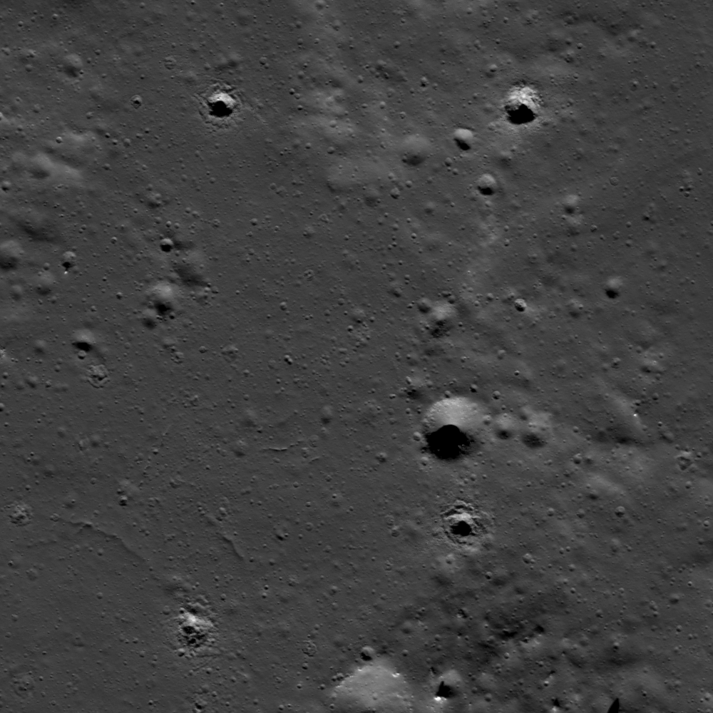
In appearance much like driveway gravel, these boulders at the bottom of the cobra-head formation of a prominent sinuous rille in the Vera-Prinz region of Oceanus Procellarum would dwarf most houses. By far, the largest of the boulders (26.3353°N, 43.71077°W), isolated at upper right, is 28 meters wide. Full 41 cm resolution mosaic of LROC NAC frames M168488930L spacecraft orbit 9964, August 20, 2011; angle of incidence 43.79° from 26.43 km [NASA/GSFC/Arizona State University].
Belated corrections - Like the Moon, like the geological rate of change in the data in those vast catalogs, many of the posts appearing here have staying power!

Because of a busy season near the end of 2011, not long after the first bulk publication of many of these dramatic close-ups, in the LROC Planetary Data System release of December 15, 2011, we grabbed a quick look at a few of them and failed to return afterward to properly re-sample them.

Even backed away and resampled to 4 meters resolution, revealing the boulder field's location on the floor of the Vera formation (26.32°N, 316.28°E), the cobra head of a sinuous rille in Oceanus Procellarum, the level of detail visible in this LROC NAC frame is remarkable [NASA/GSFC/Arizona State University].
Uncorrected, these images first appeared here in a series of posts in late December, and having had the error pointed out nine months later, right about the time of our 3000th post since 2006, perhaps we can find time over the course of the remainder of our lives to correct all the other embarrassing errors also.

Life is short, but the "inconstant Moon" is just about eternal.

Context is nearly a necessity when presenting LROC NAC derivative imagery. Vera is demonstrated in this simulated perspective from NASA's ILIADS application to be more than merely the cobra-head of a sinuous rille. It appears to be a cobra-head within a cobra-head, emerging as many similar formation on the Moon do, from beyond the rim of a crater that, at some point after its formation, was inundated by fresh melt. Another example is Plato. Perhaps Prinz, now a nearly buried ghost crater, was flooded twice [NASA/GSFC/LMMP/Arizona State University].

Friday, September 14, 2012

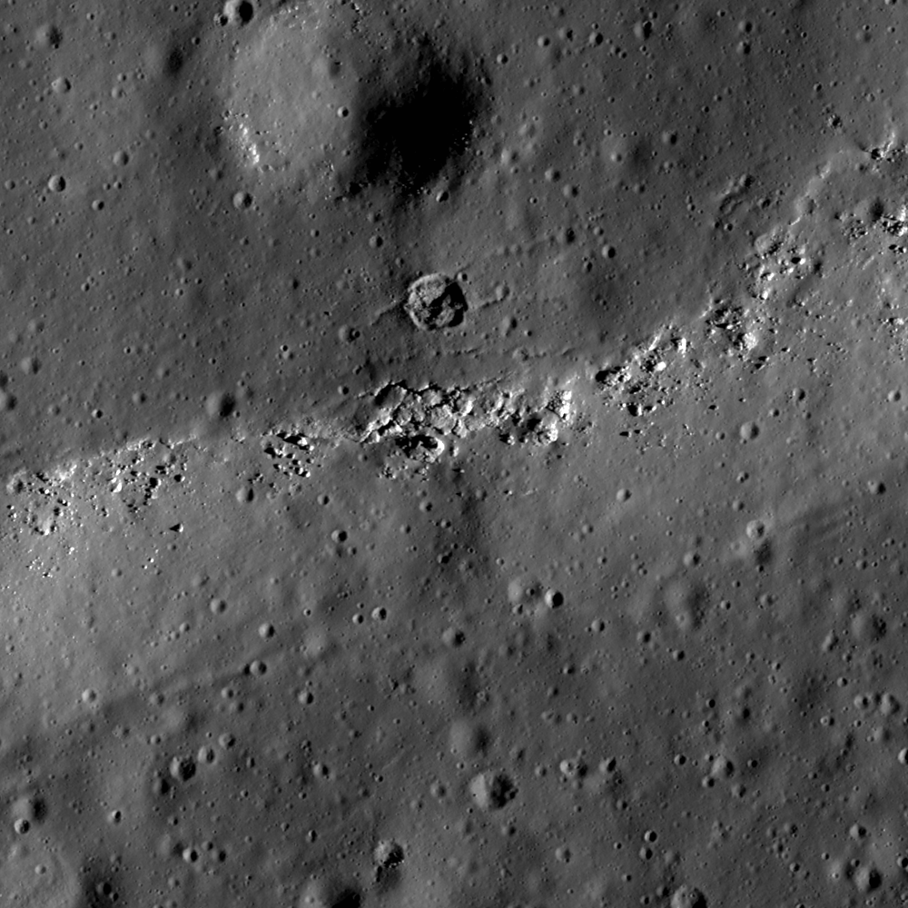
LROC: Veneer of Melt

A veneer of impact melt rock erodes away the surface just north of Newcomb crater in the lunar highlands. A 406 meter-wide field of view from LROC Narrow Angle Camera (NAC) frame M162026367LE, LRO orbit 9012, June 6, 2012; angle of incidence 73.95° over 0.91 meter per pixel resolution, from 43.88 kilometers. (View the 700 meter-wide field of view shown in the LROC Featured Image, released September 14, 2012, HERE.) [NASA/GSFC/Arizona State University].
Drew Enns
LROC News System

Impact melt forms in most impacts on the Moon. The melt shown here was emplaced during the impact event that produced Newcomb crater (29.76° N, 43.67° E). Rather than producing a melt pond or flow in this location, the melt here formed a thin veneer that cooled and formed a rigid crust. The melt veneer is now identifiable thanks to a thin scarp along its margin with boulders breaking from it. Two cracks split a small crater on the melt veneer, indicating the crater formed after the melt solidified.

A larger crater is less pronounced, so perhaps it was covered by the melt as it was deposited. But how was this thin deposit of melt originally emplaced?

Newcomb crater is in center in this context image. The arrow points to the area shown at high-resolution in the LROC Featured Image, a veneer of melt located on Newcomb's northern ejecta blanket. Note the large smooth surfaces on the crater's floor. LROC Wide Angle Camera (WAC) 100 meter resolution Global monochrome mosaic, field of view 100 kilometers across. [NASA/GSFC/Arizona State University].
Most impact melt normally stays inside a crater, forming flows and ponds on terraces, and resulting in flat floors. Often, a small portion of the melt is sloshed out of the crater and forms spectacular forms on the ejecta blanket. Some of the ejected melt flows down the flanks until it finds a depression and pond. But not all of the melt makes it to the depression as some melt solidifies on the slope. The result is a thin film of impact melt covering the shallow slopes of the crater flank, like we see in the today's Featured Image!

Explore more impact melt, inside and outside Newcomb, crater in the full LROC NAC frame, HERE.

Related Posts:
Boulder on the Edge
Splish Splash
An Impact Melt Veneer in the Highlands
King crater's unusual melt pond

Simulated view of the same WAC mosaic above draped over LOLA 128 point-per-degree elevation model (v.2) from a perspective 10 km over the eastern side of Newcomb, looking northwest. ILIADS application, NASA LMMP.
A more recent look, from a higher altitude (147.13 km), shows the erosion of melt in context with local topography, especially three distinct melt ponds north of Newcomb. LROC NAC frame M180887966R, spacecraft orbit 11774, January 11, 2012; incidence angle 72.63° at 1.46 meters resolution [NASA/GSFC/Arizona State University]/

Replay of Armstrong rites at National Cathedral

Neil Armstrong, the first man on the lunar surface, passed away August 25. His remains were interred at sea after private memorials in his native Ohio earlier this month.   On Thursday morning, September 13, Dr. Armstrong's family, his fellow astronauts along with notables in American government attended a state memorial conducted at the National Cathedral in Washington.

C-SPAN in the United States broadcast the service live, and they have scheduled re-plays of that coverage through the weekend and in days following. The entire service is now available on-line HERE, together with past interviews with Dr. Armstrong and other relevant information. The re-play runs 1 hour and 19 minutes.


Thursday, September 13, 2012

Rogozin presses Russian lunar base, Chandrayaan-2 delayed by Proton and Phobos-Grunt investigations

As Russia’s Deputy Prime Minister Dmitry Rogozin continues to deployment of a manned base lunar base 'by 2020,' ISRO declines comment on Chandrayaan-2 delay 'until 2016' India's follow-up to its successful first lunar orbiter, together with a small remotely operated rover landed on the Moon by a Russian spacecraft had previously been delayed to 2013 and 2013 [ISRO/IKI].
According to Russian and Indian sources, Russian Prime Minister Dmitry Rogozin continues to lobby for  a permanent station on the lunar surface "before 2020," calling it an "over-arching task," a "super goal," or очень задача for the Russian state, "stimulating the development of science and industry."

Reports followed an interview recorded on Vesti FM Radio earlier this month.

“Russian cosmonauts learned to work in orbit and gained needed experience there," Rogozin said. "Why shouldn't they try to build a full-scale lunar base to set the groundwork for further leaps in science?”

Indian press reports have covered the interview in context with little more information than previously known about Russia's planned role in Chandrayaan-2. Indian Space Research Organisation (ISRO) chief K. Radhakrishan recently declined comment on reports that the Chandrayaan-2 lunar orbiter, lander and rover mission will now be unavoidably delayed until 2016.

"For Chandrayaan-2, Russia has to provide the lander, and India will build the lunar orbiter and rover," Radhakrishan said. "Russia has said they would come to us with a decision (regarding their grunt-class Luna-Resurs lander) after their reviews.”

Russia is reviewing their inter-planetary missions in light of recent set-backs, particularly following the November failure of Phobos-Grunt  and, more recently, after the failure of Sino-Russian vehicle that was tied to a faulty Proton booster.

The results of at least one such investigation, into the Proton failure, were reported out September 12, according to Anatoly Zak of RussianSpaceWeb.com.

Chandrayaan-2 had already been delayed until 2014, planned for launch on India's troubled Geosynchronous Satellite Launch Vehicle (GSLV).  Radhakrishnan confirmed ISRO will prepare the booster, the lunar orbiter and rover, but he declined comment on a report from Russia that India’s second lunar mission must be delayed until at least 2016.

Lev Zelyony, head of the Russian Space Research Institute (IKI), said in February the Luna-Resurs lander might not be ready before 2016.

“There were plans to launch the Luna-Glob and Luna-Resurs missions in 2015,” Zelyony told RIA Novosti in February. “But dates may have to be moved, because the NPO Lavochkin-design for the ill-fated Phobos-Grunt vehicle are integral also to Russia's planned unmanned lunar projects and "clearly need to be reviewed.”

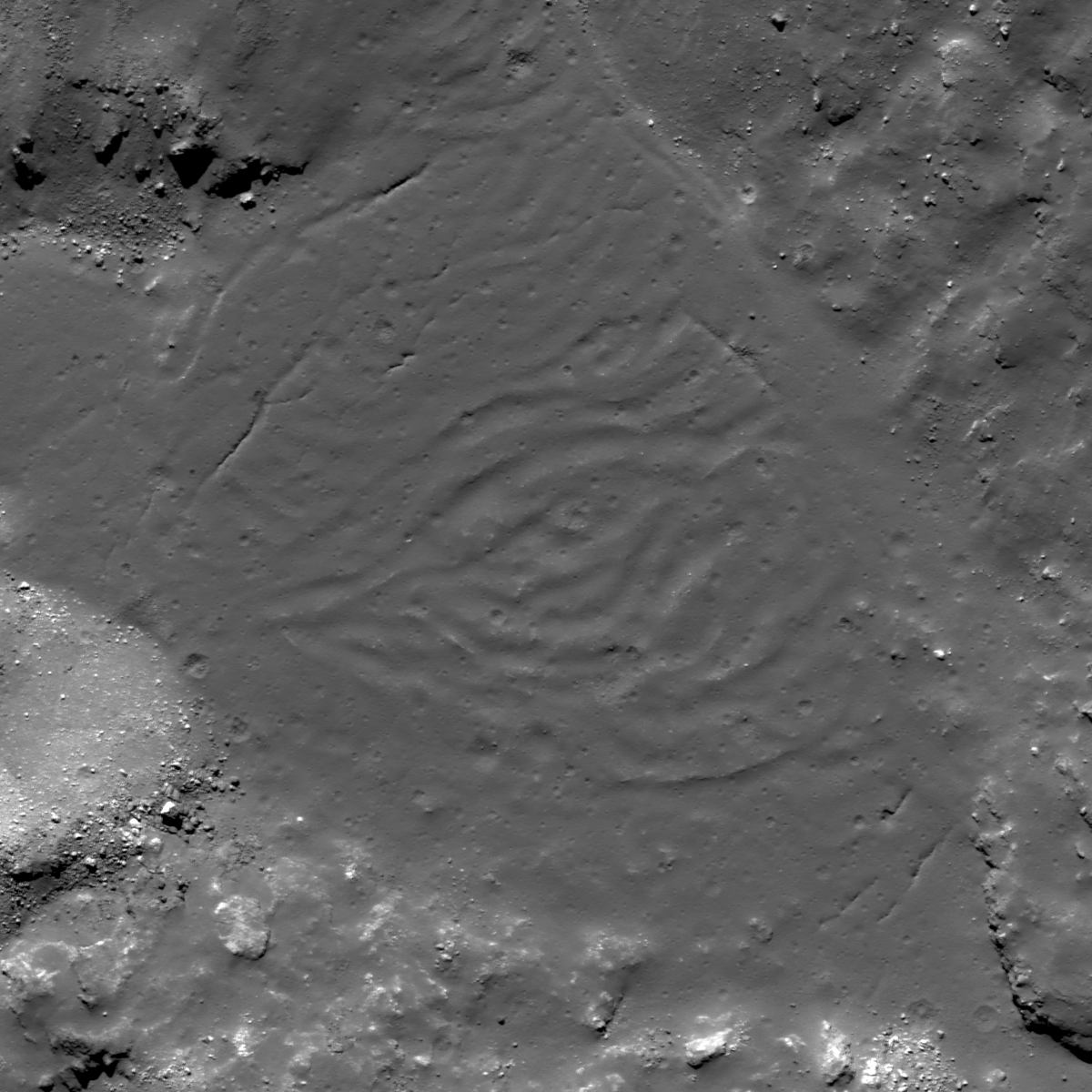
Rippled Pond on Tycho's Wall

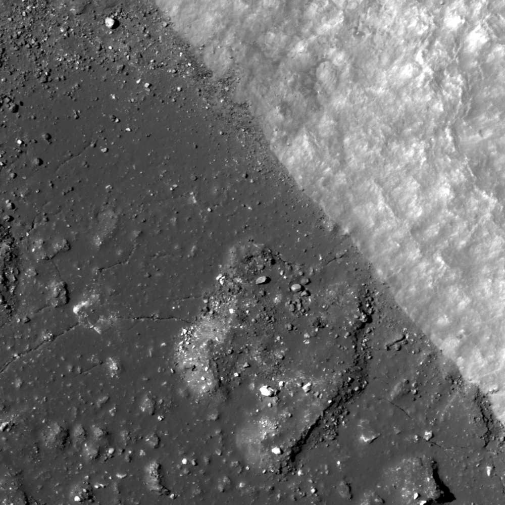
A melt pool on Tycho's northeastern wall has a rippled, somewhat wrinkly texture. Why might the surface look this way? 792 meter-wide field of view from LROC Narrow Angle Camera (NAC) frame M185947368R, spacecraft orbit 12481, March 9, 2012; angle of incidence 45.21° at 66 cm resolution from 63 kilometers. View the full-sized LROC Featured Image, HERE [NASA/GSFC/Arizona State University].
Lillian Ostrach
LROC News System

By now, it should be obvious that Tycho crater has many spectacular geologic features. Numerous Featured Images have explored the crater, its ejecta, and impact melt deposits. Today's Featured Image focuses on a melt pond located in the northeastern crater wall terraces (42.469°S, 349.672°E).

The pond is relatively isolated, having formed in a depression where the melt pooled after streaming down the crater wall, and does not appear to connect to other, smaller melt ponds along the break in wall-slope. Above and below the pond is the thickly veneered crater wall, but the wall below the pool is rougher and the melt veneer is more fragmented and exhibits some mass-wasting erosion.

An in-depth look at the melt pond reveals linear cracks that have been partially filled in with thin regolith. These cracks may represent cooling cracks that formed as the pond cooled and decreased volume, where some melt at the pond edge remained "stuck" as the remainder of the pond cooled and contracted. Alternatively, the fractures may have formed in the thinnest portion of impact melt, possibly representing changes in the underlying topography, which is probably variable and uneven in the chaotic wall terrace material. However, take a look at the center of the pond - what do you see?

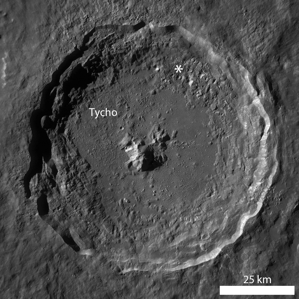
LROC Wide Angle Camera (WAC) monochrome mosaic of Tycho, showing the location of the area at high resolution in the LROC Featured Image released September 13, 2012 noted with an asterisk [NASA/GSFC/Arizona State University].
The center of the melt pond is deformed in a vaguely wrinkly, broad wave-like rippled region. The ripples are contained in the pond center in an approximate circular shape except for an elongation toward the left of the image. What could this morphologic feature possibly be? The ripple morphology is similar to the texture you might observe when removing the surface skin off a glass of hot milk with a spoon. The surface skin (or crust) on the milk deforms due to the force of the spoon as you gently attempt to collect the milk-skin before adding your hot cocoa mix and marshmallows. Consider a geologic example: as pahoehoe lava flows down the pali (steep slope) in Hawaii, the surface of the flow begins to cool and a crust forms. As the lava continues to flow downhill, the cooling lava slows down but the hotter lava uphill continues to flow fast, so the cooling lava begins to deform and wrinkle.

Might this process be applied to the Moon? Sure! Tightly wrinkled, deformed impact melt is visible in the exterior flows at Tycho where there is a prominent change in surface slope. However, the melt pond in the Featured Image is not precisely like these exterior flows, but perhaps there is enough slope change beneath the pond to have affected the cooling melt and thus form these undulating ripples. Right now, we simply do not know, but a detailed scientific study focused on the occurrence, morphology, and topography of these types of features may provide a better understanding of the geologic story of these features.

How many melt ponds can you find in Tycho's terraced walls in the full LROC NAC image, HERE? Do any of these ponds have a ripply, somewhat wrinkled texture?

Related Posts:
Tycho's flash-frozen inferno
River of Rock
Tycho Central Peak Spectacular!
View From the Other Side
Breached Levee

The "miracle boys of Minsk" captured this forenoon image of Tycho, part of a full disk monochrome mosaic, from Belarus September 20, 2010. This is the familiar view of the 109 million year "young" crater. One of their fabulous color images of Тихо can be viewed HERE [Astronominsk].

Wednesday, September 12, 2012

September 12, 1962

Anaxagoras exterior melt

Exterior impact melt ponded to the east of high-latitude Anaxagoras crater. A roughly 1.8 km-wide field of view from LROC Narrow Angle Camera (NAC) M185949707L, LRO orbit 12482, March 9, 2012; angle of incidence 73.08° at 1.76 meters resolution from 180 kilometers. View the 1000 x 1000 pixel original LROC Featured Image HERE [NASA/GSFC/Arizona State University].
Lillian Ostrach
LROC News System

Impact melt drastically altered the landscape in and surrounding Anaxagoras crater (73.458°N, 349.934°E, ~52 km diameter). Previous Featured Images focused on the interior melt pond and melt-covered mounds, but the exterior ponds are important, too. Impact crater formation is violent: all of the energy associated with a moving bolide is imparted to the target immediately upon impact. Some of the energy may vaporize the impactor, while a substantial amount of the energy is responsible for excavating the crater cavity. In many cases, some of the target rocks are heated to their melting temperatures (~1300°C for basalt, ~1500°C for anorthosite) to form impact melt. Once formed, impact melt may be excavated in a similar manner to unconsolidated ejecta. Some melt remains in the crater interior, pooled on the crater floor and terraces and forming a veneer on the crater walls, while some melt is emplaced on or near the crater rim. Similar to the crater interior, the immediate exterior of the crater may be veneered with impact melt and exhibit melt channels and flows, as well as exterior melt ponds.

LROC WAC monochrome (604 nm) mosaic, stitched from 10 sequential passes on March 21, 2011, shows a roughly 80 km-wide view of Anaxagoras and vicinity, itself situated on the rim of Goldschmidt to the east. Image center is 72.4°N, 350.0°E. The the location of the area detailed in the LROC Featured Image released September 12, 2012 is indicated by the yellow arrow [NASA/GSFC/Arizona State University].
The opening image by itself might be mistaken for a smooth mare region because there was enough impact melt to coalesce into a pond and evenly bury the underlying surface, but the WAC context image (above) shows this not to be the case everywhere. On the flanks of the eastern rim of Anaxagoras, the melt pond is very smooth in some areas (opening image, left) while relatively rougher elsewhere (opening image, right), which may indicate that this melt pond did not have enough volume to completely obscure the preexisting surface. In the very smooth portion, there are some fractures similar to those observed in other melt ponds. There are also several impact craters with irregular morphologies. These craters, all less than 100 m in diameter, may have these different morphologies for several reasons related to target properties. The 94 m diameter crater in the upper right may be irregular because the crater punched through a thin resistant layer of impact melt rock to the looser unconsolidated preexisting surface. Other nearby craters may have formed in partially molten melt or may have formed much later, after a thin layer of regolith was generated by micrometeorites. Additional study of superposed crater morphology on impact melt, paired with analog laboratory experiments, may help distinguish the difference between impacts into a partially molten material and those into a layered target (previously studied in depth by Drs. Oberbeck and Quaide, among others).

What do you think?  Take some time to examine the exterior impact melt ponds in the full LROC NAC image, HERE.

Breached Levee

A closer look, at more than twice the resolution, we see one of the more prominent features on the impact melt pond in LROC NAC frame M185949707L, subject of the LROC Featured Image released September 12, 2012. LROC NAC M122252864L, spacecraft orbit 3150, March 3, 2010. The resolution available from only 43 km above during this earlier fly-over was 48 cm per pixel [NASA/GSFC/Arizona State University].

Tuesday, September 11, 2012

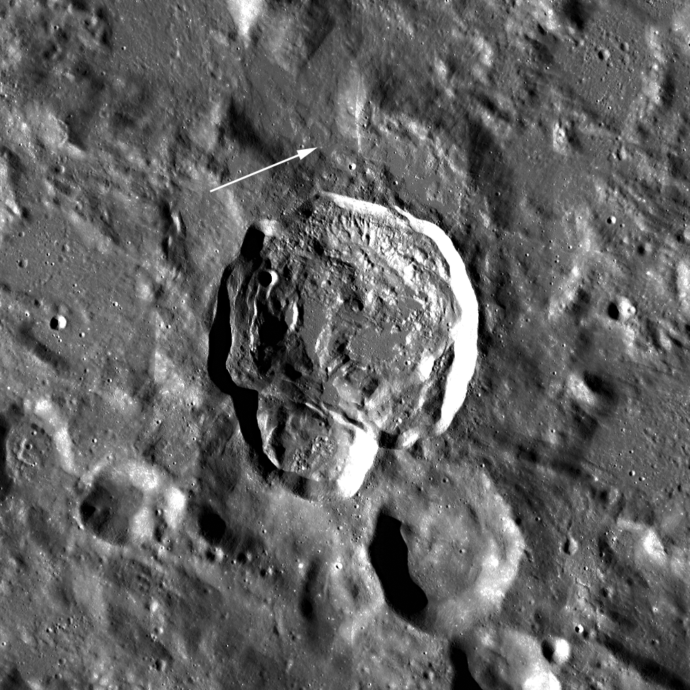
Breached Levee at Tycho

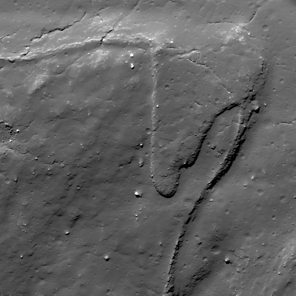
Impact melt breached a levee to flow downhill on the terraced walls of Tycho. Downslope is toward image bottom, re-sampled from the roughly 500 meter-wide field of view seen in the LROC Featured Image released September 11, 2012, itself derived from LROC Narrow Angle Camera (NAC) observation M170634588L, spacecraft orbit 10280, September 14, 2011; angle of incidence 41.67° at 50 cm per pixel resolution, imaged from 45.9 kilometers [NASA/GSFC/Arizona State University].
Lillian Ostrach
LROC News System

The geology within and surrounding Tycho crater is nothing short of spectacular. LROC images have shown the beauty of Tycho's 2 km-tall central peak, the morphology of impact melt on the crater floor, and the complexity of the exterior impact melt flows. Today's Featured Image once again highlights a geologically fascinating impact melt flow located on a terrace of Tycho's northern wall (42.428°S, 349.190°E).

When substantial amounts of impact melt are generated during the impact process, evidence of ejected melt is observed in the form of exterior melt ponds and flows, as well as veneers and channels within the crater walls. Whether interior melt coalesces to form channels or flows on the crater walls depends on numerous factors, including the viscosity of the melt and the volume of melt distributed on the walls. As melt cools, it becomes more viscous and less prone to flow, and thin veneers of melt splashed on crater walls will cool very quickly compared to thick melt ponds. However, if lots of melt is splashed onto the crater walls, the melt may coalesce and take longer to cool, perhaps allowing flows to form with the increased volume of melt. Channels, however, are believed to require melts of higher temperature (low viscosity) in order to form levees and mechanically and/or thermally erode the terrain in which the channels form. Knowing this information, can you explain the impact melt morphology in the opening image?

LROC WAC (GLD100) monochrome mosaic draped over LOLA altimetry elevation data (128ppd, v.2) in LMMP ILIADS simulated perspective over Tycho crater (85 km diameter). Arrow notes location of field of view shown at high-resolution in LROC Featured Image released September 11, 2012. View original LROC WAC context image HERE [NASA/GSFC/Arizona State University].
The opening image is an area on the northern terraced wall of Tycho that is covered in impact melt. Since Tycho wasn't formed yesterday, a thin regolith layer covers the melt (created by small impacts and micrometeorite impact gardening) and there are boulders eroding out of the slope. Cracks, softened by the thin regolith, abound in this region, and probably represent cooling cracks. There is a levee-like feature winding from the upper left to the lower right that probably was formed by impact melt that coalesced and flowed down the interior walls, essentially representing the flow boundary. However, a tongue-like flow obscures a portion of the levee-like boundary. Assuming that a large volume of melt was channelized where the inside of the channel was toward the right side of the opening image, this late-stage small flow (or drip) bypassed the leveed wall on its descent toward the crater floor. Where did the material composing the small flow come from? Perhaps some melt from the surrounding walls flowed toward the levee-like boundary but got "stuck" and pooled on the top portion of the levee, until the weight of material overcame the levee barrier. Or maybe the tongue-like flow represents a late-stage splash of melt that was ejected and then landed on the wall to drip down toward the crater floor.

What do you think? Scour the full LROC NAC image, HERE, and see what other impact melt morphologies you can find!

Related Posts:

Marshall's new-generation lunar lander flies again

Overcast skies didn't deter the "Mighty Eagle," flying high above the historic F-1 test stand, once used to test turbopumps for the Saturn booster first stage engines [NASA/MSFC/Dennis Olive].
Long under development, completing a round of flight test objectives, following up on a successful August 28 pre-programmed flight profile test, the "Mighty Eagle," NASA robotic prototype lunar lander, flew to 30.48 meters (100 feet) and descended gently to a controlled landing during a successful free flight September 5 at NASA's Marshall Space Flight Center (MSFC) in Huntsville, Alabama.

Guided by autonomous rendezvous and capture software, the vehicle located an on-ground target using an on-board camera and then flew directly to the target on its own. 

The flight of August 28 followed a pre-programmed flight profile, but the test on September 5 operated "closed loop," with the vehicle seeking and finding its target using internal software to guide its flight.

"The ‘Mighty Eagle’ had a great flight, fulfilling the objectives we had for this test -- finding and landing on its target using a closed-loop system," said Greg Chavers, test lead for the project. "Given this is one of our last tests in this series, it is a worthy finale of a lot of people’s hard work -- including our young engineers. They did a remarkable job running today’s flight."

New for this test, the "Mighty Eagle" project managers turned over the vehicle’s keys to three young Marshall engineers, Adam Lacock, flight manager; Jake Parton, test conductor; and Logan Kennedy, systems engineer.

Nicknamed the "Mighty Eagle" after one of the characters in the popular "Angry Birds" game, the vehicle is a three-legged prototype that resembles an actual flight lander design. It is 4 feet tall and 8 feet in diameter and, when fueled, weighs 700 pounds. It is a “green” vehicle, fueled by 90 percent pure hydrogen peroxide The vehicle is guided by an on-board computer that activates thrusters to power the craft’s movements.

"We’ve surpassed our expectations and flew the most challenging run to date," said Mike Hannan, a controls engineer in Marshall's Engineering Directorate. "It was an overcast, extremely humid day, and we were concerned steam might block the vehicle’s camera. We didn’t see that, and the lander sought and found its target successfully."

"It was an invaluable experience managing today’s test,” added Lacock. "This is the kind of experience young engineers, like myself, need to learn more about flight mechanics, vehicle hardware and project management. It was a good day for our team."

NASA will use the "Mighty Eagle" to mature the technology needed to develop a new generation of small, smart, versatile robotic landers capable of achieving scientific and exploration goals on the surface of the moon, asteroids or other airless bodies.

The "Mighty Eagle" was developed by the Marshall Center and Johns Hopkins University Applied Physics Laboratory in Laurel, Md., for NASA’s Planetary Sciences Division, Headquarters Science Mission Directorate. Key partners in this project include the Von Braun Center for Science and Innovation, which includes the Science Applications International Corporation, Dynetics Corp., and Teledyne Brown Engineering Inc., all of Huntsville.

Related and Background Posts:
Mighty Eagle lander 100 foot flight at Redstone (November 4, 2011)
New Robotic Lander Prototype skates tests (January 29, 2011)
NASA update; ILN Anchor Nodes and Robotic Lunar Lander Project (August 17, 2010)
The Lunar Quest Program and the International Lunar Network (September 6, 2009)

ILOA to study deep space from Chang'e-3

Steve Durst, founding director of ILOA, and Jun Yan, Director General of NAOC, after signing Memorandum of Understanding for collaboration on galaxy imaging from Chang'e-3 on the lunar surface [ILOA].
Keith Stein
DC Space News Examiner

The International Lunar Observatory Association (ILOA) in Hawaii has signed a Memorandum of Understanding with the National Astronomical Observatories (NAOC), Chinese Academy of Sciences, to use a telescope on China‘s Chang'e-3 lunar lander, still planned for launch in 2013.

The MOU was signed during a ceremony that took place in Kamuela, Hawaii on Sept. 4.

“This science collaboration will be part of a mission that will conduct the first soft controlled landing of any spacecraft on the Moon in almost 40 years” the ILOA said in a statement on Friday.

"It will be the first ever program to conduct astronomical imaging from the lunar surface." ILOA Founding Director Steve Durst noted.

China’s NAOC is responsible for the ultraviolet lunar telescope onboard the Chang'e-3 lander, which will be operated by the China National Space Administration (CNSA).

Related Posts:
Remote-operated Moon-based deep space telescope concept demonstrated in Hawai'i (July 26, 2012)
Will China deploy first lunar rover since 1976? (April 30, 2012)
SpaceDev flies prototype hybrid rocket lunar lander (December 20, 2007)

Other Chang'E-3 Related Posts, HERE.

Chang'e-3 lunar lander - stationary science platform illustrated together with planned remote-operated lunar rover may be deployed at Sinus Iridum in 2013 [Lunar Pioneer].

2012 Geological Society of America, Annual Meeting & Exposition, Charlotte, NC - 4-7 November


New Moon Rising: The Latest Geologic Results from the Lunar Surface
Charlotte Convention Center: 213BC
8:00 AM-12:00 PM, Wednesday, 7 November 2012

Paper No. 224-15: LUNAR ORIENTALE BASIN: A COMPREHENSIVE CONCEPTUAL MODEL FOR THE ORIGIN OF BASIN RINGS AND GEOLOGICAL UNITS FROM NEW SPACECRAFT DATA -- James HEAD, David M.H. BAKER, Gregory A. NEUMANN, David E SMITH, Maria T. ZUBER, and William M. VAUGHAN

Paper No. 224-6: TESTING HYPOTHESES OF ORIGIN FOR LUNAR FLOOR-FRACTURED CRATERS: VISCOUS RELAXATION VERSUS MAGMATIC INTRUSION AND PREDICTIONS OF ASSOCIATED GRAVITY ANOMALIES -- Lauren JOZWIAK, James W. HEAD, Maria T. ZUBER, David E. SMITH, David E. and Gregory NEUMANN

Paper No. 224-1: EXPLORING THE MOON WITH LRO: CHARACTERIZING VOLCANISM ON THE LUNAR SURFACE -- Samuel J. LAWRENCE, B.L. JOLLIFF, Timothy GLOTCH, B. Ray HAWKE, Benjamin T. GREENHAGEN, Julie STOPAR, Mark ROBINSON, W. Brent GARRY, and J. Olaf GUSTAFSON

Paper No. 224-14: CONSTRUCTION AND EROSION IN THE FORMATION OF LUNAR SINUOUS RILLES -- Tracy GREGG, Carolyn ROBERTS, and R. Aileen YINGST

Paper No. 103-5: CHARACTERISTICS OF SMALL-SCALE GRABEN ON THE MOON DISCOVERED BY THE LUNAR RECONNAISSANCE ORBITER CAMERA (LROC) -- Renee FRENCH, Craig BINA, Mark ROBINSON, and Donna M. JURDY


Paper No. 224-9: LRO DIVINER LUNAR RADIOMETER EXPERIMENT RESULTS -- David Paige

Paper No. 202-6: STATISTICS OF SMALL LUNAR CRATERS: ORIGIN OF DIFFERENCES BETWEEN IMPACT MELT AND EJECTA UNITS -- Carolyn H. VAN DER BOGERT, Harald HIESINGER, Colin DUNDAS, Lillian OSTRACH, Mark ROBINSON, Alfred MCEWEN, and Michael ZANETTI


Canadian Lunar Exploration Light Rover prototype

Stylized View of the Lunar Exploration Light Rover (LELR) Design, Figure 3 from "A Canadian Lunar Exploration Light Rover Prototype," McCoubry & Langley, et al, (Sept. 2012).
McCoubrey & Langley, et al
MacDonald, Dettwiler, and Associates, CANADA
Centre de technologies avancées BRP – Universite de Sherbrooke
University of Toronto Institute for Aerospace Studies

CANADA

In 2010, the Canadian Space Agency (CSA) commenced the Lunar Exploration Light Rover (LELR) project as part of its Exploration Surface Mobility program. The LELR project consists of building rovers, integrating them with tools and instruments, and executing representative mission deployments. The LELR is designed for mobility tasks related to science prospecting, in-situ resource utilization (ISRU), and future upgrades for crew transportation. The vehicle is based on a rugged, custom mobility platform built by Bombardier Recreational Products Centre for Advanced Technology.

Onboard sensors provide feedback and situational awareness for tele-operation, autonomy, and onboard control (future upgrade). Modular onboard software is used to ensure future upgradeability, and offers such features as localization without external aids and visual teach and repeat software developed by the University of Toronto. Future work may involve adding onboard human control, further integration with payloads and deployments in coordination with the international space exploration community.

Figure 2: "Artist’s Concept of the Lunar Exploration Light Rover’s Various Mission Configurations."
In the context of returning systems to the surface of the Moon, there have been several recent developments in the area of Lunar mobility. The Chariot rover is a large-class system designed to carry astronauts and perform regolith moving tasks such as bulldozing. The Eurobot Ground Prototype (EGP) rover is a medium-class system designed to accomplish both science exploration and transport of a single standing astronaut. The Scarab rover is a small-class rover designed to carry resource prospecting instruments and sensors. The goal of the Lunar Exploration Rover (LELR) program is to develop a mobility solution that can accomplish all of these tasks and thereby provide a flexible and versatile platform for development and testing including integration with exploration tools and instruments. This will then allow development and simulation of analogue mission scenarios. The LELR vehicle is a key part of the Canadian Space Agency (CSA) Exploration Surface Mobility program.

The remainder of this paper will discuss the mission scenarios used to define the LELR requirements, the LELR design, and the current program status and upcoming test plan.

View the full paper, HERE.

Some Related Posts

Monday, September 10, 2012

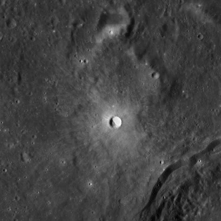
LROC: Boulder or Crater?

A roughly circular feature near Albufeda E, in the Moon's nearside southern highlands. A 140 meter-wide field of view from LROC Narrow Angle Camera (NAC) observation M175212953R, LRO orbit 10955, November 6, 2011; angle of incidence 44.11° at 40 cm per pixel resolution from 24.26 km overhead [NASA/GSFC/Arizona State University].
Sarah Braden
LROC News System

At first glance, the object in the center of today's Featured Image may look like a crater. The direction of illumination is from the right-to-left. What may look like a crater is actually a boulder about 29 meters across, which is just one meter shy of the length of a blue whale!

The lighting in the image and the circular appearance of the boulder may initially fool the human eye into interpreting this feature as a crater. However, there are several important clues in the image which clearly indicate that we are indeed looking at a boulder. Click on the image for a full resolution version. First, notice the other smaller boulders in the image. These are identified as boulders because they are irregular in shape, and relatively higher reflectance compared to the surrounding impact melt. Next, look at the direction of the shadows of the boulders. The boulders are all positive topographic features and cast shadows in the same direction. In contrast, a crater is a negative topographic feature. Looking at the full resolution version of the Featured Image shows many small craters in the surrounding impact melt. Look at these craters and compare them to the boulders until your eyes interpret the boulders as topographic highs and the craters as lows. If you still have difficulty, pick up your laptop and rotate the image 180 degrees (rotating your head might be more convenient).

NASA LMMP ILIADS simulated perspective of the area of interest projected from a point 40 km over the Moon and 100 km east. LROC Wide Angle Camera WAC Global Mosaic (100m) draped over LOLA digital elevation model shows Abulfeda E and its larger neighbor Abulfeda A. The red asterisk marks the location of the area seen at exceptionally high resolution in the LROC Featured Image released September 9, 2012 [NASA/GSFC/Arizona State University].
This field of boulders is located on the eastern side of the crater Abulfeda E, a Copernican-aged crater in the highlands, located at 16.769°S, 10.141°E and is 5.6 km in diameter. Many other large boulders are scattered around in the impact melt deposits surrounding the crater. Some of the boulders are partially buried by impact melt and debris.

Explore the entire NAC image HERE.

Related Posts:
"Boulder 668" at Descartes C
If you were an Astronaut, would you land here?
Weaving boulder trails on the Moon
Boulder on the Edge
Sunset Boulder
LROC QuickMap WAC-NAC mosaic of Albefuda E sampled at 8 meters resolution. From the WAC-derived and laser altimetry (LOLA)-derived DEM it appears the northeastern rim of Albefula E where the large boulder feature is situated (arrow), does not rise above the landscape, unlike an area further south, on the eastern slope,  where a large boulder field has accumulated [NASA/GSFC/Arizona State University].

Sunday, September 9, 2012

Free Enterprise and 'New Space'

Enterprise in space: Free markets or government subsidies?
Paul Spudis
The Once & Future Moon
Smithsonian Air & Space

Free Enterprise:  Business governed by the laws of supply and demand, not restrained by government interference, regulation or subsidy – also called free market.

Rick Tumlinson of the Space Frontier Foundation published a “free-enterprise” critique of the Republican platform in regard to the American civil space program. Indeed, the text of the space plank is vague (no doubt intentionally, so as to give the candidate maximum flexibility to structure the space program to align with his vision and goals for the country).  But what I found most interesting was the underlying premise and assumptions in Tumlinson’s article, a worldview that I find striking.

In brief, Tumlinson approves of the current administration’s direction for our civil space program.  The U.S. has stepped back from pushing toward the Moon, Mars and beyond and redirected NASA on a quest for “game-changing” technologies (to make spaceflight easier and less costly), while simultaneously transitioning launch to low Earth orbit (LEO) operations to private “commercial space” companies selected by our government to compete for research and development funding and contracts.  Many see this as gutting NASA and the U.S. national space program.  To be clear, the term “commercial space” in this context does not refer to the long-established commercial aerospace industry (e.g., Lockheed-Martin, Boeing) but to a collection of startup companies dubbed “New Space” (typically, companies founded by internet billionaires who have spoken much and often about lofty space plans, but have actually flown in space very little).

Tumlinson criticizes the Republican space plank because it does not explicitly declare that a new administration would continue the current policy.  In his view, the very idea of a federal government space program, including a NASA-developed and operated launch and flight system, is a throwback to 1960’s Cold War thinking.  Instead, he envisions space as a field for new, flexible and innovative companies, untainted by stodgy engineering traditions or bloated bureaucracy.  Many space advocates on the web hold this viewpoint – “If only government would get out of the way and give New Space a chance, there will be a renaissance in space travel!”  But travel to where?  And why?

The idea that LEO flight operations should be transitioned to the commercial sector is not new.  It was a recommendation of the 2004 Aldridge Commission report on implementing the Vision for Space Exploration (VSE).  NASA itself started the Commercial Orbital Transportation Services program (COTS) in 2006, designed to nurture a nascent spaceflight industry by offering subsidies to companies to develop and fly vehicles that could provision and exchange crew aboard the International Space Station.  That effort was envisioned as an adjunct to – not a replacement of – federal government spaceflight capability.

The termination of the VSE and the announcement of the “new direction” in space received high cover from the 2009 Augustine committee report, which concluded that the current “program of record” (e.g., Constellation) was unaffordable.  The Augustine Committee received presentations with options to reconfigure Constellation whereby America could have returned to the Moon (to learn how to use resources found in space) under the existing budgetary cap, but they elected to start from first principles.  Hence, we have something called Flexible Path, which doesn’t set a destination or a mission but calls on us “to develop technology” to go anywhere (unspecified) sometime in the future (also unspecified).  With target dates of 2025 for a “possible” human mission to a near-Earth asteroid and a trip to Mars “sometime in the 2030’s,” timelines and milestones for the Flexible Path offer no clarity or purpose.  Try getting a loan or finding investors using a “flexible” business plan.

Tumlinson argues that both political parties should embrace this new direction because New Space will create greater capability for lower cost sooner.  He also makes much about the philosophical inclinations of the Republican Party (the “conservative” major party in American politics) – Why don’t the Republicans support free enterprise in space?  Why are they putting obstacles in the way of all these new trailblazing entrepreneurs?  As to those obstacles, it is unclear exactly what they are.  True enough, there are regulatory and liability issues with private launch services, but not of such magnitude that they cannot be handled through the traditional means of indemnification (e.g., launch insurance).

The COTS program record of the past decade largely has not been a contract let for services, but a government grant for the technical development of launch vehicles and spacecraft.   Close reading reveals the real issue:  Tumlinson wants more of NASA’s shrinking budget to finance New Space companies. He is concerned that a new administration might cut off this flow of funding.  However, what will cut off the flow of funding is having no market, no direction, and no architectural commitment – regardless of who occupies the White House.

The belief of many New Space advocates is that once they are established to supply and crew the ISS, abundant and robust private commercial markets will emerge for their transportation services.  Although many possible services are envisioned, space tourism is the activity most often mentioned.  Whether such a market emerges is problematic.  Although Richard Branson’s Virgin Galactic has a back-listed manifest of dozens of people desiring a suborbital thrill ride (at a cost of a few hundred thousand dollars), those journeys are infinitely more affordable than a possible orbital trek (which will cost several tens of millions of dollars, at least initially).  Nevertheless, there will no doubt be takers for a ticket.  But what will happen to a commercial space tourism market after the first fatal accident?  New Space advocates often tout their indifference to danger, but such bravado is neither a common nor wise attitude in today’s lawsuit-happy society (not to mention, the inevitable loss of confidence from a limited customer base).  My opinion is that after the first major accident with loss of life, a nascent space tourism industry will become immersed in an avalanche of litigation and will probably fully or partly collapse under the ensuing financial burden.  We are no longer the barnstorming America of the 1920’s and spaceflight is much more difficult than aviation.

Despite labeling themselves “free marketers,” New Space (in its current configuration) looks no different than any other contractor furiously lobbying for government sponsorship through continuation of its subsidies.  True free-market capitalists do not seek government funding to develop a product.  Rather, they devise an answer to an unmet need, identify a market, seek investors and invest their own capital, provide a product or service and only remain viable by making a profit through the sale of their goods and services.

Tumlinson bemoans the attitude of some politicians, ascribing venal and petty motives as to why they do not fully embrace the administration’s new direction, e.g., the oft-thrown label “space pork” to describe support for NASA’s Space Launch System.  In regard to New Space companies, Tumlinson asserts that, “[We] have to both give them a chance and get out of the way.”  But in fact, he does not want government to “get out of the way” – at least not while they’re still shoveling millions into New Space company coffers – nor when they need (and they will) a ruling on, or protection of, their property rights in space.  Any entity that accepts government money is making a “deal with the devil,” whereby it is understood that such money comes with oversight requirements (as well it should, consisting of taxpayer dollars).

"Questions about the vision boil down to whether we want to incorporate the Solar System in our economic sphere, or not.” – Presidential Science Advisor John Marburger, 2006

Successful commercialization of space has occurred in the past (e.g., COMSAT) and will occur in the future.  But the creation of a select, subsidized, quasi-governmental industry is not by any stretch of the imagination what we commonly understand free market capitalism to mean.  It is more akin to oligarchical corporatism, a common feature of the post-Soviet, Russian economy.  True private sector space will be created and welcomed, but not through this mechanism, whose most worrisome accomplishment to date has been to effectively distract Americans from noticing the dismantling of their civil space program and preeminence in space.

Originally published at his Smithsonian Air & Space blog The Once and Future Moon, Dr. Spudis is a senior staff scientist at the Lunar and Planetary Institute. The opinions expressed are those of the author and are better informed than average.