Friday, January 31, 2014

Collapsing tube in Oceanus Procellarum

Collapsing Tube, Oceanus Procellarum
Uneven depression near the north end of Rima Suess, west of Kepler in Oceanus Procellarum. Image centered on 9.109°N, 311.396°E; field of view 1.38 km; LROC Narrow Angle Camera (NAC) observation NAC M1112132406L, spacecraft orbit 16148, January 6, 2013; illumination from the west an an incidence angle of 67° at 1.14 meters per pixel resolution from 113.56 km [NASA/GSFC/Arizona State University].
Hiroyuki Sato
LROC News System

Rima Suess is one of many sinuous rilles on the Moon. Located in Oceanus Procellarum between the Marius Hills and Kepler crater, it is about 165 km long and trends in a NNW-SSE direction. Sinuous rilles often exhibit meandering channels, which may have formed as open channels or lava tubes which subsequently collapsed.

About 1 km north from the northern end of Rima Suess, there are 5-7 enclosed, irregularly aligned sinuous depressions (see next NAC context image). These are likely all related to another Sinuous rille (about 30 km long) at the north of these depressions (see WAC context image). The opening image highlights the southern, less well-developed tail of one of these irregularly-aligned sinuous depressions. The subsidence here seems to have proceeded unevenly and then stopped, although it is possible that the subsidence is still ongoing, albeit very slowly.   

North Rimae Suess (LROC NAC)
Northern portion of Rima Suess from LROC NAC mosaic M1112132406LR, centered near 9.22°N, 311.45°E, field of view about 9.2 km across. White box outlines field of view in LROC Featured Image released January 31, 2014 [NASA/GSFC/Arizona State University].
The enclosed, isolated depressions indicate the potential collapse of a subsurface void, which in this case is likely to have been lava tubes. One potential hypothesis is that the thickness of the lava tube roof in this region of the Moon is variable, so in some places the roof is thinner (meaning less strong) than in other places.  The thinner roofs would be more prone to collapse, resulting in a partially collapsed tube and the discontinuous channels in the Rima Suess area that you see today.

Oceanus Procellarum, Rimae Seuss
LROC Wide Angle Camera (WAC) context view of Rima Suess, centered on 9.38°N, 311.38°E. LROC NAC M1112132406LR footprint outlined in blue, with the location of the area shown at high resolution in the Featured Image marked with a yellow arrow [NASA/GSFC/Arizona State University].
One of the lunar pits, which are possible entrances to the subsurface voids, are located in the middle of a sinuous rille near the Marius Hills. Even though no pits had been observed in this northern Rima Suess area, the subsurface caves could be still there, waiting for us to explore.

Enjoy the full resolution NAC mosaic of Rima Suess, HERE.

Related LROC Posts:
Depths of Mare Ingenii
How Common are Mare Pit Craters?
New Views of Lunar Pits
Sublunarean void!
Impact Melt Pit
Diversity of Basaltic Lunar Volcanism
Sinuous Chain of Depressions
Secrets of Schröteri
Marius Hills Pit - Lava Tube Skylight?

Geologic characteristics: Chang’E-3 exploration region

From extensive data distilled from remote sensing collected by the DIVINER Lunar Radiometer on-board the Lunar Reconnaissance Orbiter (LRO) since July 2009 has allowed David Page and the DIVINER team to produce extensive maps of the thermal behavior "and a range of derived quantities at the Chang'e-3 landing site, described in a separate report released January 5. Distinct areas can be seen in LROC WAC Surveys, with an overlay mapping rock abundance using thermal dissipation temperatures collected at the coldest periods, before local sunrise. DIVINER detected no minimum temperatures in the area below 94°K [NASA/JPL/UCLA/GSFC/ASU].
Zhao, Huang & Qiao, et.al.
Planetary Science Institute
China University of Geosciences, Wuhan

Science China (March 2014)

ABSTRACT: We present topographic, geomorphologic and compositional characteristics of a 1°×1° (~ 660 square kilometer) region centered near the landing site of Chang’E-3 using the highest spatial resolution data available. We analyze the topography and slope using Digital Terrain Model (DTM) generated from Terrain Camera (TC) images. The exploration region is overall relatively flat and the elevation difference is less than 300 meters, and eighty percent of the area slopes are less than 5°. 

Impact craters in the exploration region are classified into four types based on their degradation states. We investigate the wrinkle ridges visible in the exploration region in detail, using TC and Lunar Reconnaissance Orbiter (LRO) Narrow Angle Camera (NAC) images. We calculate iron oxide and titanium dioxide abundances using Multispectral Imager (MI) data and confirm two basaltic units: the northern part, belonging to Imbrium era low-titanium to very-low titanium mare basalts, and the southern part is Eratosthenian era low titanium to high titanium mare basalts. 

Finally, we produce a geological map and propose the geologic evolution of the exploration region. 

M177x3C_604nm-anot-580x800
The north central Mare Imbrium exploration region and landing site of Chang'e-3.  The geology report dates the northern mare to the Imbrium Age and the southern mare, in the lander's immediate vicinity to the Eratosthenian age, two billion years apart. LROC WAC mosaic swept up in three sequential orbits, December 5, 2011; sunrise angle of incidence 76° at 61.5 meters per pixel resolution, from 44.7 km [NASA/GSFC/Arizona State University].
INTRODUCTION: Nearly 40 years after the completion of the Apollo and Luna missions, the third Chinese lunar mission, Chang’E-3 (CE-3), was launched on December 2, 2013 and safely landed on the surface of the Moon on December 14, 2013.

The rover “Yutu” separated from the lander successfully about 8 hours later. The landing site of CE-3 is 44.12°N, 340.49°E, which is located in the northern part of Mare Imbrium. As the first Chinese lunar soft-lander and rover, the landing site was selected primarily considering engineering constraints, including topography, communication and solar illumination.

In addition, local geologic diversity was also taken into consideration, including impact craters, wrinkle ridges, and basaltic materials of different ages. The CE-3 landing site and its nearby terrains have never been visited by any other missions. Therefore, the exploration will shed light on the geologic characteristics, geochemical diversity and evolution of Mare Imbrium.

Geological maps in Apollo era and recent studies reveal regional geologic information for Sinus Iridum and the adjacent terrains. However, the spatial resolution of previous maps is not sufficient for detailed geologic study or for the rover traverse planning considering both scientific and engineering requirements. Luckily, as unprecedented high spatial resolution remote sensing data being acquired by recent lunar missions (e.g., Chang’E 1 & 2, SELENE-1, Chandrayaan-1 and Lunar Reconnaissance Orbiter: LRO), large scale geological mapping and detailed study were possible for prior study of the Chang'e-3 landing site and its exploration region. 

Read or Download the Full Adobe PDF file HERE.

ESA on Yutu, as controllers wait for sunrise, February 9

Yutu
Song of Yutu. China News reported panorama photographs of the Chang'e-3 lander captured by Yutu and corresponding images of the Jade Rabbit rover from the lander, prior to the end of their second 330 hour-long lunar day, January 25, were the final such complimentary photographs of the mission [CAS/CNSA/CLEP].
Professor Bernard H. Foing
Bernard Foing
Executive Director
International Lunar Exploration Working Group (ILEWG).

ESA SMART-1 Project scientist

The Chang'e3 lander and Yutu rover achieved impressive results in their first lunar day on the surface, where temperatures are over 90°C (194°F) at midday. After their first lunar night, which is extreme, with temperatures dropping to -180°C (-292°F), they spectacularly woke up and resumed operations after January 12.

This was already an achievement considering the very difficult thermal conditions and surface environment on the Moon. Already with our SMART-1 (2003) spacecraft orbiting the Moon we had to solve thermal problems, but it is much more difficult for a rover on the surface.

Unofficial information mentions a mechanical problem during the withdrawal of a solar panel on rover Yutu prior to sleep on January 25 for the second night. This could affect the electronic box and a few instruments on the rover mast.

Operations of the Chang'e-3 lander instruments would not be affected.

1. Is it likely that lunar dust caused a mechanical failure, meaning the rover could not hibernate?  It is not established that dust is the culprit at this stage. The high thermal extremes from day to night (from 90° to –180°C, or 194° to -292°F) can also certainly put a huge stress and fatigue on mechanical systems.

2. What can be done to protect future rovers from lunar dust?  Already measures are being taken by rover designers to avoid dust entering sensitive mechanical gear or depositing on optical surfaces. However lunar dust can be electrostatically charged and can stick on sensitive parts.

3. Is Yutu no longer operational, or could it be fixed?  Our Chang’e 3 and Yutu colleagues can be praised for what they have achieved so far. I am sure that they are not going to give up. They are analyzing, in depth, the problem and are working hard to assess safe recovery strategies.

4. How will this failure restrict the remaining mission?  The lander went nominally to sleep (January 25). The Yutu rover sent an emotional farewell message before hibernating. For the Yutu rover we have to hope and wait for the next lunar morning (around February 9) to assess the situation. Best wishes from all of us to the Yutu lunar Jade Rabbit.

We wish the teams and Change3 Yutu good luck and success for further operations. Lunar exploration is difficult, but these technical challenges bring progress for future lunar and planetary missions and even for applications in space and on Earth.

Related Posts:
Problem with solar-powered Yutu rover before nightfall (January 25, 2014)
Chang'e begins long-term science mission (January 18, 2014)
Preliminary Science Results from Chang'e-3 (January 16, 2014)
Chang'e-3 and Yutu survive first lunar night (January 14, 2014)
Chang'e-3 APXS delivers its first surface analysis (January 1, 2014)
Chang'e-3 lander and Yutu rover from LRO (December 31, 2013)
6 of 8 Chang'e-3 science instruments now active (December 18, 2013)
LRO: Finding Chang'e-3 (December 15, 2013)
China's Jade Rabbit, it's time in the Sun (December 15, 2013)
Chang'e-3 Landing Site in Mare Imbrium (December 15, 2013)
Jade Rabbit successfully deployed to the lunar surface (December 14, 2013)
It's not bragging if you do it (December 9, 2013)
"Lunar Aspirations" - Beijing Review (December 9, 2013)
Chang'e-3 safely inserted into lunar orbit (December 6, 2013)
CCTV: Chang'e-3, launch past TLO to Earthview (December 2, 2013)
Chang'e-3 launched from Xichang (December 1, 2013)
Chang'e-3 launch window opens 1 December 1730 UT (November 29, 2013)
Helping China to the Moon, ESA (November 29, 2013)
'Government Penalty' removed from Google Lunar XPRIZE terms (November 7, 2013)
Chang'e-3 and LADEE: The Role of Serendipity (October 31, 2013)
Outstanding animation celebrates China's Chang'e-3 (October 29, 2013)
LROC updates image tally of human artifacts on the Moon (September 25, 2013)
Chang'e-3: China's rover mission (May 4, 2013)
China's grand plan for lunar exploration (October 11, 2012)
ILOA to study deep space from Chang'e-3 (September 11, 2012)
China's Long March to the Moon (January 14, 2012)
China plans lunar research base (May 11, 2011)
PRC continues methodical program (March 8, 2011)
Chang'e-2 arrives in mission orbit (October 9, 2010)
Dispatch from Chang'e-2: Sinus Iridum (October 4, 2010)
Chang'e-2 takes direct approach (October 1, 2010)
Chang'e-2 sets stage for future lunar missions (September 3, 2010)
Chang'e-1 research reported published (July 22, 2010)
Chandrayaan-1 goes silent (August 29, 2009)

Thursday, January 30, 2014

LROC captures LADEE at 9 km

LADEE 9 km from LRO (LROC NAC)
NASA's Lunar Atmosphere and Dust Environment Explorer (LADEE) caught zooming 9-km below LRO, all the more amazing since the spacecraft orbit the Moon in orbits perpendicularly to one another, or 90° out of phase. LROC NAC M1144387511LR  [NASA/GSFC/Arizona State University].
Mark Robinson
Principal Investigator
Lunar Reconnaissance Orbiter Camera (LROC)
Arizona State University

Teamwork! Imaging NASA's Lunar Atmosphere and Dust Environment Explorer (LADEE) spacecraft with LROC required extremely precise timing, worked out by the LADEE, LROC, and LRO operations teams. LADEE is in an equatorial orbit (east-to-west) while LRO is in a polar orbit (south-to-north).

By happenstance the two spacecraft are occasionally very close - on 15 January the two came within 9 km of each other. Since LROC is a pushbroom imager, it builds up an image one line at a time, thus catching a target as small and fast as LADEE is tricky! Both spacecraft are orbiting the Moon with velocities near 1600 meters per second (3600 mph), so timing and pointing of LRO needs to be nearly perfect to capture LADEE in an LROC image.

LADEE 9 km from LRO (LROC NAC)
LADEE smeared out against the lunar background. Image expanded 4x, lunar scene 81 meters wide, LADEE about 2 meters in the long direction [NASA/GSFC/Arizona State University].
LADEE passed directly beneath the LRO orbit plane a few seconds before LRO crossed the LADEE orbit plane, meaning a straight down LROC image would have just missed LADEE. Now is where the careful planning came into play. The LADEE and LRO teams worked out the solution: simply have LRO roll 34° to the west so the LROC detector (one line) would be in the right place as LADEE passed beneath.

As planned at 8:10:51.693 PM EST on 14 January 2014 LADEE entered the NAC field of view for 1.35 milliseconds and a smeared image of the intrepid spacecraft was snapped. LADEE appears in four lines of the LROC NAC-R, and is distorted right-to-left. What can we see in the LADEE pixels in the NAC image?

Geometrically corrected image of LADEE, 4x enlargement[NASA/GSFC/Arizona State University].
Step one is to minimize the geometric distortion in the smeared lines that show the spacecraft. However, in doing so the background lunar landscape becomes distorted and unrecognizable (see above). The scale (dimension) of the NAC pixels recording LADEE is 9 cm (3.5 in), however, since the spacecraft were both moving about 1600 meters per second the image is blurred in both directions by around 50 cm. So the actual pixel scale lies somewhere between 9 cm and 50 cm, thus even with geometric correction LADEE is a bit blurry. Despite the blur it is possible to find details of the spacecraft, which is about 1 meter wide and 2 meters long. You can see the engine nozzle, bright solar panel, and perhaps a star tracker camera (especially if you have a correctly oriented schematic diagram of LADEE for comparison).

Computer generated image of LADEE oriented and illuminated as
it was during the close pass with LRO
[NASA ARC/LADEE].
LADEE was designed to study the Moon's thin exosphere and the lunar dust environment. An “exosphere” is an atmosphere that is so thin that molecules do not collide with each other. This exosphere is so tenuous that the number of molecules in a given volume at the Moon is less than the number of molecules in the same volume of space outside the International Space Station..

Dissolve animation with NAC image of LADEE and labeled LADEE graphic
degraded to match NAC resolution
[NASA/GSFC/ARC/Arizona State University].
LADEE is still early in its mission. One of the more exciting moments so far was observing how the lunar exosphere changed as the Chinese lander Chang'e 3 set down on the Moon on 14 December 2013. There was concern that the exhaust plume might spread out and mix with native molecules causing a contamination problem for the LADEE measurements, but so far no problem.

Find LADEE in the NAC left/right mosaic, the irregular shape of the image is due to topography and the off-nadir slew (hint: LADEE coordinates sample 9514, line 19827), HERE.

Related LROC Featured Images:
Impact!
Mountains of the Moon

Tuesday, January 28, 2014

Boulders on a hill on the floor of Rutherfurd crater

Boulders on the floor of Rutherford (LROC NAC)
Knobby surface of Rutherfurd crater floor, 1050 meter-wide LROC NAC field of view centered on 61.340°S, 348.085°ENAC M1123653329R, spacecraft orbit 17669, May 20, 2013; incidence angle 81° from 50.83 km  [NASA/GSFC/Arizona State University].
Hiroyuki Sato
LROC News System

Today's Featured Image highlights a bumpy hill adjacent to a large melt pool (now frozen to solid rock) inside Rutherfurd crater (48 km in diameter). As seen in the WAC context image below, the floor is mostly littered with materials that collapsed and slumped from the crater wall, and with impact melts filling the topographic lows.

Uphill is to the left of the image, here you can see a wrinkled/fractured surface, likely formed as a thin rigid sheet of frozen melt. Over time this melt rock slowly broke apart -- the source of other boulders. The boulders slowly migrate downhill, breaking themselves apart, a form of mass wasting similar to that seen on Earth. However there is a big difference, almost all the energy on the Moon is provided by a continual rain of small meteorites, whereas on the Earth erosion is driven by plate motion induced earthquakes, and weathering.

Rutherfurd crater (LROC WAC)
49.98 km Rutherfurd crater (61.15°S, 346.278°E), nested on the rim of more famed, much wider and older Clavius, in the nearside southern highlands. The area captured at high-resolution and released as the LROC Featured Image, January 28, 2014, is marked with an arrow. LROC WAC global mosaic [NASA/GSFC/Arizona State University].

Rutherfurd from Earth (Damian Peach)
Rutherfurd as viewed from Earth by experienced astrophotographer Damian Peach, November 20, 2005. "Rutherfurd is located entirely within the southern rim of much larger Clavius," he writes. "Rutherfurd is somewhat oval in shape, with the long axis oriented approximately in a north-south direction. The rim is overlaying the inner wall of Clavius, and thus the rim of Rutherfurd is higher above the surface along the north and west sides. The floor is irregular in shape, and there is a central peak somewhat offset to the northeast. The ejecta pattern; oblong shape, and location of the central peak indicate the original impact may have been at a low angle from the southeast [Damian Peach].
Rutherfurd on the rim of Clavius (LROC WAC)
49.98 km Rutherfurd (61.15°S, 346.278°E), nested on the southeastern rim of more famed, much wider and older Clavius, in the nearside Southern Highlands. The area captured at high-resolution and released as the LROC Featured Image, January 28, 2014, is marked with an arrow. LROC WAC global mosaic [NASA/GSFC/Arizona State University].
Explore the floor of Rutherfurd crater in the full NAC frame with very low sun, HERE.

Related Posts:
Central Peak of Rutherfurd
Rough Crater Wall Surface
Sinuous Cracks
View From The Other Side
Cracked mound
A beautiful bench crater (Rutherfurd)

Saturday, January 25, 2014

Problem with solar-powered Yutu rover before nightfall

CCTV Yutu rover on the Moon
China's Yutu, "Jade Rabbit," lunar rover, the first such vehicle operated on the Moon since 1976 [CCTV].
Official sources in Beijing report China's lunar rover Yutu “experienced a mechanical abnormality" and "scientists are organizing repairs."

The problem occurred “due to the complicated lunar surface environment," just before local sunset at the Chang’e-3 landing site on Saturday, January 25, Xinhua reported, citing a report from SASTIND, China’s State Administration of Science Technology and Industry for National Defense.

No further details were available from official sources early Sunday, Beijing time (UT +8 hours).

Unofficial sources, however, say the rover's solar panels may have failed to retract when ground controllers were preparing Yutu for hibernation ahead of local sunset on Saturday, and the start of a second 330 hour-long lunar night since successful deployment from the Chang’e-3 lander, December 14.

Whether the anomaly permanently disables the rover may be undetermined. Both the Chang’e-3 lander and Yutu depend on solar power, so communicated efforts to resolve the issue may have had to be suspended before nightfall to conserve a base of power to sustain the small robot through the long night ahead.

Retracted solar panels also may be critical to protecting the rover’s components over the two weeks of cold and darkness before the next local sunrise on February 9. The Mare Imbrium landing site’s latitude, with its higher angles of incidence sunlight than available at the equator, might require the lander and rover both experience a shorter period of peak charging, a shorter time when the Sun is higher in the sky, than strictly the time between dawn and dusk.

Meanwhile, with no problems of its own reported, the stationary Chang'e-3 lander, Xinhua reported, successfully began its own second 14 day-long period of required dormancy period on Friday.

After their first hibernation periods ended two weeks ago the optical telescope carried out observations using an extreme ultraviolet (UV) camera, observing Earth’s plasma-sphere, which is among other successful operations reported among “Preliminary Science Results” released by the Chinese Academy of Sciences a week ago.

UHF communications between the lander and Yutu were also successfully tested.

The Chang'e-3 mission makes China only the third nation to soft-land a spacecraft on the Moon, the first since Luna 24 in 1976, and whatever the outcome of its present challenges, Yutu is only the third remote- operated rover deployed on the Moon since Lunokhod 2 in 1973, which also used solar power but was kept warm through four lunar nights using heat generated by a radioisotope decay heater.

Some Related Posts:
Chang'e begins long-term science mission (January 18, 2014)
Preliminary Science Results from Chang'e-3 (January 16, 2014)
Chang'e-3 and Yutu survive first lunar night (January 14, 2014)
Chang'e-3 APXS delivers its first surface analysis (January 1, 2014)
Chang'e-3 lander and Yutu rover from LRO (December 31, 2013)

Thursday, January 23, 2014

A colorful history of floor-fractured Komarov

Small fresh crater in Komarov
A small, fresh crater dots the wall of a fracture in the floor of Komarov crater. An approximately 2.5 km-wide field of view from LROC NAC frame M130653607, LRO orbit 4388, June 8, 2010; incidence angle 71.7° at 63 cm per pixel resolution from 60.73 km [NASA/GSFC/Arizona State University].
H. Meyer
LROC News System

A small, fresh crater can be seen on the right side of Today's Featured Image on the floor of Komarov crater. The crater was formed when an impactor smashed into the wall of one of the fractures (or graben) in the crater floor. Some of the ejecta from the impact can be seen draping the wall of the graben. This graben is one of many in the floor of Komarov.

Komarov, best seen in the context image below, is known as a floor-fractured crater whose fractures likely formed through intrusive magmatic activity. The western portion of Komarov crater has been modified by the deposition of smooth, low albedo material and the formation of floor fractures. Is this the same low albedo mare basalts that filled nearby Mare Moscoviense?

Virtual view from an imaginary point 93 km over the lunar farside, south of Komarov. The LROC 302 ppd WAC mosaic draped over LOLA 128 laser ppd topography shows how pyroclastic flow overran the mare-filled Moscoviense floor. Both the famous long floor and Komarov are each well inside the larger, circular and less obvious Moscoviense basin [NASA/GSFC/LMMP/Arizona State University].

Komarov (context)
LROC Wide Angle Camera (WAC) context image of the western interior, wall and rim of floor-fractured Komarov, outlining the LROC Featured Image field of view (yellow), released January 22, 2014, with the frame of the LROC NAC observation from which it was derived outlined in red [NASA/GSFC/Arizona State University].
WAC2_Moscoviense-1560x1125
LROC WAC context image of Komarov crater (~80 km in diameter) relative to Mare Moscoviense (centered at 27.282°N, 148.122°E). The red box denotes the full NAC frame from which Today's Featured Image was taken. Image field of view is approximately 450 km wide [NASA/GSFC/Arizona State University].
Though Komarov is located on the edge of Mare Moscoviense, it is not covered in the same smooth, low albedo mare basalts that are seen in the Moscoviense basin today (See WAC context image above and Clementine false-color image below). Compositional differences in and around Mare Moscoviense indicate multiple episodes of volcanic activity. Three bands (415 nm, 750 nm, and 1000 nm) from the Clementine UVVIS camera were used to create the false-color image below. The three bands were ratioed to control the colors of the false-color image. The 750/415 ratio controls the red component, which is an indication of low titanium or high glass content as found in mature lunar regolith and to a greater degree pyroclastic deposits. The 750/1000 ratio controls the green component and is an indicator of the amount of iron on the surface. The 415/750 ratio controls the blue component and indicates high titanium or bright slopes and albedos.

Clementine-1994-multispec-Komarov-1238x886
Clementine false-color multi-spectral mosaic of Komarov and Mare Moscoviense. The dashed circle denotes the rim of Komarov and the white arrow points to a fresh crater from the full NAC frame. Field of view approximately 180 km across [NASA/DOD/USGS/Arizona State University].
Notice in the false-color image above that Mare Moscoviense appears blue (higher in titanium since we know Mare Moscoviense is a low albedo feature), whereas Komarov appears red. Even within Komarov, the western side is more red (likely pyroclastics or low-titanium basalts) than the eastern side, which is comparable to deep red of the surrounding highlands (mature regolith). A crater in the NAC frame from which Today's Featured Image was taken appears bright blue and stands out from the rest of Komarov's floor. This bright blue color is likely due to the fact that this crater is fresh and has brought up unweathered (fresh) higher albedo material from depth. The fresh crater from the opening image is too small to be seen in the Clementine false-color image.

Investigate this complex region for yourself, HERE.

Related Posts:
Fresh crater in Komarov's fractured floor
Bah Humboldt!
Gassendi's Fractures
Atlas
Karpinskiy Floor Fractures

Tuesday, January 21, 2014

Clementine - The Legacy, Twenty Years On

Engineering model of the Clementine spacecraft in the Lunar Exploration Vehicles exhibit at the National Air and Space Museum. Interstage and solid rocket motor (bottom half) was discarded before insertion into lunar orbit.
Paul D. Spudis
Smithsonian Air & Space

The first spacecraft to globally map the Moon left lunar orbit on May 3, 1994.  Clementine, a joint Department of Defense-NASA mission, had systematically mapped the Moon’s surface over 71 days, collecting almost 2 million images.  For the first time, scientists could put results of the Apollo lunar sample studies into a regional, and ultimately, a global context.  Clementine collected special data products, including broadband thermal, high resolution and star tracker images for a variety of special studies.  But in addition to this new knowledge of lunar processes and history, the mission led a wave of renewed interest in the processes and history of the Moon, which in turn, spurred a commitment to return there with both machines and people.  We peeked into the Moon’s cold, dark areas near the poles and stood on the edge of a revolution in lunar science.

Prior to Clementine, good topographic maps only existed for areas under the ground tracks of the orbital Apollo spacecraft.  From Clementine’s laser ranging data, we obtained our first global topographic map of the Moon.  It revealed the vast extent and superb preservation state of the South Pole-Aitken (SPA) basin and confirmed many large-scale features mapped or inferred from only a few clues provided by isolated landforms.  Correlated with gravity information derived from radio tracking, we produced a map of crustal thickness, thereby showing that the crust thins under the floors of the largest impact basins.

Two cameras (with eleven filters) covered the spectral range of 415 to 1900 nm, where absorption bands of the major lunar rock-forming minerals (plagioclase, pyroxene and olivine) are found.  Varying proportions of these minerals make up the suite of lunar rocks.  Global color maps made from these spectral images show the distribution of rock types on the Moon.  The uppermost lunar crust is a mixed zone, where composition varies widely with location.  Below this zone is a layer of nearly pure anorthosite, a rock type made up solely of plagioclase feldspar (formed during the global melting event that created the crust).  Craters and large basins act as natural “drill holes” in the crust, exposing deeper levels of the Moon.  The deepest parts of the interior (and possibly the upper mantle) are exposed at the surface within the floor of the enormous SPA basin on the far side of the Moon.

Topographic map of the Moon made from Clementine laser altimetry in mid-latitudes and stereo images near the poles. Large depression in southern far side is the South Pole-Aitken basin.
Clementine showed us the nature and extent of the poles of the Moon, including peaks of near permanent sun-illumination and crater interiors in permanent darkness.  From his first look at the poles, Gene Shoemaker (Leader of the Clementine Science Team) got an inkling that something interesting was going on there.  Gene was convinced that water ice might be present, an idea about which I had always been skeptical.  At that time, no trace of hydration had ever been found in lunar minerals and the prevailing wisdom was that the Moon is now and always had been bone dry.  With Gene arguing to keep an open mind and Stu Nozette (Deputy Program Manager) devising a bistatic radio frequency (RF) experiment to use the spacecraft transmitter to “peek” into the dark areas of the poles, we moved ahead on planning the observations.

To my astonishment (and delight), a pass over the south pole of the Moon showed evidence for enhanced circular polarization ratio (CPR) – a possible indicator of the presence of ice.  A control orbit over a nearby sunlit area showed no such evidence.  However, CPR is not a unique determinant for ice, as rocky, rough surfaces and ice deposits both show high CPR.  It took a couple of years to reduce and fully understand the data, but collection of the bistatic collection was successful.  In part, our ice interpretation was supported by the discovery of water ice at the poles of Mercury (a planet very similar to the Moon).  We published our results in Science magazine in December 1996, setting off a media frenzy and a decade of scientific argument and counter-argument about the interpretation of radar data for the lunar poles (an argument that continues to this day, despite subsequent confirmation of lunar polar water from several other techniques).

Along with Clementine’s success came a growing interest in lunar resources and a new appreciation for the complexity of the Moon.  This interest led to the selection of Lunar Prospector (LP) as the first PI-led mission of NASA’s new, low-cost Discovery series of planetary probes.  LP flew to the Moon in 1998 and carried instruments complementary to the data produced by Clementine, including a gamma-ray spectrometer to map global elemental composition, magnetic and gravity measurements, and a neutron spectrometer to map the distribution of hydrogen.  LP found enhanced concentrations of hydrogen at both poles, again suggesting that water ice was probably present.  The debate on the abundance and physical nature of the water ice continued, with estimates ranging from a simple enrichment of solar wind implanted hydrogen in polar soils, to substantial quantities of water ice trapped in the dark, cold regions of the poles.

Buttressed by this new information, the Moon became an attractive destination for robotic and human missions.  With direct evidence for significant amounts of hydrogen (regardless of form) on the surface, there now was a known resource that would support long-term human presence.  This hydrogen discovery was complemented by the identification in Clementine images of several areas near the pole that remain sunlit for substantial fractions of the year – not quite the “peaks of eternal light” first proposed by French astronomer Camille Flammarion in 1879 but something very close to it.  The availability of material and energy resources  – the two biggest necessities for permanent human presence on the Moon – was confirmed in one fell swoop.  Combined, the results of Clementine and LP finally gave scientists the Lunar Polar Orbiter mission we had long sought.  These two missions certified the possibility of using lunar resources to provision ourselves in space, permanently establishing the Moon as a valuable, enabling asset for human spaceflight.  Remaining was to verify and extend the radar results from Clementine and map the ice deposits of the poles.

The Clementine bistatic experiment led to the development of an RF transponder called Mini-SGLS (Space Ground Link System), which flew on the Air Force mission MightySat II in 2000.  This experiment miniaturized the RF systems necessary for a low mass, low power imaging radar.  With the 2008 inclusion of our Mini-SAR on India’s Chandryaan-1 lunar orbiter, we finally got the chance to build and fly such a system.  Chandrayaan-1 not only mapped the high CPR material at both poles, it also carried a spectrometer (the Moon Mineralogy Mapper, or M3) that discovered large amounts of adsorbed surface water (H2O) and hydroxyl (OH) at high latitudes.  Coupled with the measurement of exospheric water above the south pole by its Moon Impact Probe, Chandrayaan-1 significantly advanced our understanding of polar water, revealing it to be abundant and present in more varied forms on the Moon than had previously been imagined.

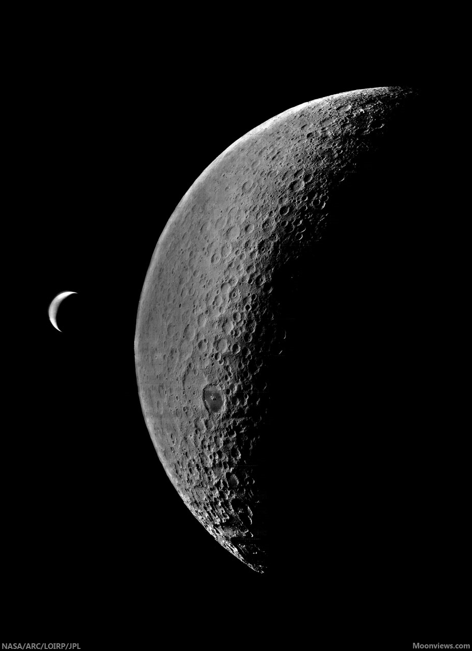
Mosaic of Clementine images of the south pole of the Moon. Dark regions contain water ice and small areas near pole are sunlit for significant fractions of the lunar day.
The ever increasing weight of evidence for the presence of significant amounts of water at the lunar poles led to the LCROSS experiment being “piggybacked” on NASA’s 2008 Lunar Reconnaissance Orbiter (LRO) mission.  LCROSS was a relatively inexpensive add-on, designed to observe the collision of the LRO launch vehicle’s Centaur upper stage with the lunar surface, looking for water in the ejecta plume of that impact.  Water in both vapor and solid form was observed, suggesting the presence of water ice in the floor of the crater Cabaeus (at concentration levels between 5 and 10 weight percent).  LRO orbits the Moon and collects data to this day.  Although much remains unknown about lunar polar water, we now know for certain that it exists; such knowledge has completely revised our thinking about the future use and habitation of the Moon.

The Clementine programmatic template has influenced spaceflight for the last 20 years.  The Europeans flew SMART-1 to the Moon in 2002, largely as a technology demonstration mission with goals very similar to those of Clementine.  NASA directed the Applied Physics Laboratory (APL) to fly Near-Earth Asteroid Rendezvous (NEAR) to the asteroid Eros in 1995 as a Discovery mission, attaining the asteroid exploration opportunity missed when control of the Clementine spacecraft was lost after leaving the Moon.  India’s Chandrayaan-1 was of a size and payload scope similar to Clementine.  The selection of LCROSS as a low-cost, fast-tracked, limited objectives mission further extended use of the Clementine paradigm.

The “Faster-Better-Cheaper” mission model, once panned by some in the spaceflight community, is now recognized as a preferred mode of operations, absent the emotional baggage of that name.  A limited objectives mission that flies is more desirable than a gold-plated one that sits forever on the drawing board.  While some missions do require significant levels of fiscal and technical resources to attain their objectives, an important lesson of Clementine is that for most scientific and exploration goals, “better” is the enemy of  “good enough.”  Space missions require smart, lean management; they should not be charge codes for feeding the beast of organizational overhead.  Clementine was lean and fast; perhaps we would have made fewer mistakes had the pace been a bit slower, but overall the mission gave us a vast, high-quality dataset, still extensively used to this day.  The Naval Research Laboratory transferred the Clementine engineering model to the Smithsonian in 2002.  The spacecraft hangs today in the Air and Space Museum, just above the Apollo Lunar Module.

It is probably not too much of an exaggeration to say that Clementine changed the direction of the American space program.  After the failure of SEI in 1990-1992, NASA was left with no long-term strategic direction.  For the first time in its history, NASA had no follow-on program to Shuttle-Station, despite attempts by Dan Goldin and others to secure approval for a human mission to Mars (then and now, a bridge too far – both technically and financially).  This programmatic stasis continued until 2003, when the tragic loss of Columbia led to a top-down review of U.S. space goals.  Because Clementine had documented its strategic value, the Moon once again became an attractive destination for future robotic and human missions.  The resulting Vision for Space Exploration (VSE) in 2004 made the Moon the centerpiece of a new American effort beyond low Earth orbit.  While Mars was vaguely discussed as an eventual (not ultimate) objective, the activities to be done on the Moon were specified in detail in the VSE, particularly with regard to the use of its material and energy resources to build a sustainable program.  Regrettably, various factors combined to subvert the Vision, thereby ending the strategic direction of America’s civil space program.

Clementine was a watershed, the hinge point that forever changed the nature of space policy debates.  A fundamentally different way forward is now possible in space – one of extensibility, sustainability and permanence.  Once an outlandish idea from science fiction, we have found that lunar resources can be used to create new capabilities in space, a welcome genie that cannot be put back in the bottle.  Americans need to ask why their national space program was diverted from such a sustainable path.  We cannot afford to remain behind while others plan and fly missions to understand and exploit the Moon’s resources.  Our path forward into the universe is clear.  In order to remain a world leader in space utilization and development – and a participant in and beneficiary of a new cislunar economy – the United States must again direct her sights and energies toward the Moon.

Note: Background history for the Clementine mission is described in a companion post at my Spudis Lunar Resources blog, HERE.

Originally published at his Smithsonian Air & Space blog The Once and Future Moon, Dr. Spudis is a senior staff scientist at the Lunar and Planetary Institute. The opinions expressed are those of the author but are better informed than average.

Wrinkled? Yes, but how old?

Wrinkle Ridge, Eastern Mare Frigoris
A wrinkle ridge formation in eastern Mare Frigoris (54.430°N, 35.670°E), from a 2 km -wide field of view from LROC Narrow Angle Camera (NAC) observation M139672711R, spacecraft orbit 5717, September 21, 2010; 56.22° incidence angle, resolution 47 cm per pixel from 38.87 km. LROC Featured Image, "Wrinkled, yes, but how old? - Released January 21, 2014 [NASA/GSFC/Arizona State University].
H. Meyer
LROC News System

Wrinkle ridges are not only some of the most striking features that wind their way across the lunar mare, but they are also extremely informative. Wrinkle ridges are the surface expression of tectonic stresses, and from observing the morphology of the ridges, we can interpret the tectonic history of the regions in which they are found.

Mare Frigoris hosts intricate systems of intertwining wrinkle ridges, suggesting a complex history. It is thought that this area was a topographic low that was later filled in with dense mare, causing the less dense anorthosite crust to sag as it underwent isostatic adjustment. The sagging resulted in compression at the surface, and the development of wrinkle ridges. As the crust was compressed it fractured, and long linear stretches of crust were pushed on top of itself thus forming these fascinating ridges.

Wrinkle Ridge, Eastern Mare Frigoris
LROC WAC context image of eastern Mare Frigoris. The full NAC field of view is outlined in red and that of the LROC Featured Image released January 21, 2014 is boxed in yellow [NASA/GSFC/Arizona State University].
The ropy appearance of the ridges in the WAC context image above are a testament to the complex motion that took place within the rock, indicating multiple directions of stress. Though most of the tectonic activity that produced wrinkle ridges in Mare Frigoris is thought to have occurred ~2.6-3.8 billion years ago, recent work suggests that wrinkle ridges may have formed in this region only 1.2 billion years ago. Believe it or not, that is young (for the Moon at least)!

Who knew wrinkles could be useful? Explore the Moon's wrinkles for yourself, HERE

Related Posts:
Bulging Wrinkle
Wrinkle Ridge in Mare Crisium
Wrinkles in Mare Frigoris
Really Wrinkled
Wrinkled Reiner Gamma
Wrinkle Ridge v Impact Crater

Saturday, January 18, 2014

Chang'e 3 begins long-term science mission

Chang'e-3 (CH-3 PCam)
Chang'e-3 lunar lander Panoramic Camera image, from a sequence released January 17. (Click on image for a wider mosaic) [Chinanews.com].
[From China Daily - January 17 (UT)] The Chang'e-3 lunar lander and rover "Yutu" have begun their long-term science mission, and will have their durability tested as it continues a survey of its landing site in northwest Mare Imbrium, sources with the Beijing Aerospace Control Center said Thursday.

The center transferred operations of the probe to a smaller management team Wednesday night, said Cui Yan, who leads the team. "We have made all the hardware and software ready for the long-term control tasks and have developed new management methods," Cui said.

Liu Junqi, one of the chief engineers on Cui's team, said during the yearlong mission the team will coordinate deep-space control stations around the nation and closely monitor the Chang'e-3 lander and Yutu to arrange scientific missions on the lunar surface.

One of major responsibility for the team is to put the lander and rover into sleep mode as the long lunar night descends and re-awaken the vehicles and their science instruments after local sunrise, Liu said. Night on the moon lasts two weeks, and the surface temperatures quickly fall below -180° C, and there is no sunlight to provide power from solar panels.

Part of a 360° panorama from the Chang'e-3 lunar lander, released with Preliminary Science Results from the Chinese Academy of Sciences, January 16 [CNSA/CLEP/CAS].

"The transfer of control marks the successful completion of the probe's first stage of exploration and scientific missions," said a publicity officer at BACC, who refused to be named. He said, under the long-term management mode, the lander and rover don't need a lot of people to take care of them. Cui's team, which has less than 20 people, is able to take over from the current large control group.

"Next, the team will control the probe to perform scientific operations that can last several months. Engineers will test whether the lander and rover can function well over a long period and whether they can live up to their designed life span," the officer added. "During the yearlong period, the team's controllers and engineers will work about 15 consecutive night shifts each month, so this is really a tough job."

Yutu, the "Jade Rabbit" lunar rover, has a designed lifespan of three months, and the lander is expected to work for one year.

After waking up following nearly two weeks of dormancy, Yutu completed its first sampling of lunar soil using its mechanical arm Tuesday, January 14, the Beijing center said. "Accuracy control of the mechanical arm at a distance of 380,000 kilometers has been realized, marking China's breakthrough in controlling a mechanical arm with high precision on the lunar surface," said Wu Fenglei from the center.

Yutu will continue to survey the moon's geological structure and surface substances and look for natural resources, while the lander will explore the landing site until the end of its life span.

Related:
Preliminary Science Results from Chang'e-3 (January 16, 2014)

NASA announces partnership opportunities for U.S. commercial lunar lander capabilities

Orion-based lander concept
Other than development of the Ares booster, the only essential program actually tossed under the bus, when Congress and the administration scrapped Constellation, was the Altair lunar lander.  Now NASA will conduct a "Pre-proposal teleconference," January 27, 2014, at 1600 (UT) and proposers will have an opportunity to ask questions about the "Lunar CATALYST" unmanned program, discussed HERE. [NASA].
Trent J. Perrotto
NASA HQ Washington

Building on the progress of NASA's partnerships with the U.S. commercial space industry to develop new spacecraft and rockets capable of delivering cargo, and soon, astronauts to low Earth orbit, the agency is now looking for opportunities to spur commercial cargo transportation capabilities to the surface of the moon.

NASA has released an announcement seeking proposals to partner in the development of reliable and cost-effective commercial robotic lunar lander capabilities that will enable the delivery of payloads to the lunar surface. Such capabilities could support commercial activities on the moon while enabling new science and exploration missions of interest to NASA and the larger scientific and academic communities.

NASA's new Lunar Cargo Transportation and Landing by Soft Touchdown (Lunar CATALYST) initiative calls for proposals from the U.S. private sector that would lead to one or more no-funds exchanged Space Act Agreements (SAA). NASA’s contribution to a partnership would be on an unfunded basis and could include the technical expertise of NASA staff, access to NASA center test facilities, equipment loans, or software for lander development and testing.

"As NASA pursues an ambitious plan for humans to explore an asteroid and Mars, U.S. industry will create opportunities for NASA to advance new technologies on the moon," said Greg Williams, NASA's deputy associate administrator for the Human Exploration and Operations Mission Directorate. "Our strategic investments in the innovations of our commercial partners have brought about successful commercial resupply of the International Space Station, to be followed in the coming years by commercial crew. Lunar CATALYST will help us advance our goals to reach farther destinations."

The moon has scientific value and the potential to yield resources, such as water and oxygen, in relatively close proximity to Earth to help sustain deep space exploration. Commercial lunar transportation capabilities could support science and exploration objectives, such as sample returns, geophysical network deployment, resource prospecting, and technology demonstrations. These services would require the ability to land small (66 to 220 pound, or 30 to 100 kilogram) and medium (551 to 1,102 pound, or 250 to 500 kg) class payloads at various lunar sites.

"In recent years, lunar orbiting missions, such as NASA’s Lunar Reconnaissance Orbiter, have revealed evidence of water and other volatiles, but to understand the extent and accessibility of these resources, we need to reach the surface and explore up close," said Jason Crusan, director of Advanced Exploration Systems at NASA Headquarters in Washington. "Commercial lunar landing capabilities could help prospect for and utilize these resources."

Lunar CATALYST supports the internationally shared space exploration goals of the Global Exploration Roadmap (GER) NASA and 11 other space agencies around the world released in August. The GER acknowledges the value of public-private partnerships and commercial services to enable sustainable exploration of asteroids, the moon and Mars.

Commercial lunar cargo transportation systems developed through Lunar CATALYST could build on lessons learned throughout NASA's 50 years of spaceflight. New propulsion and autonomous landing technologies currently are being tested through NASA's Morpheus and Mighty Eagle projects.

NASA will host a pre-proposal teleconference on Monday, Jan. 27 during which proposers will have an opportunity to ask questions about the announcement. Proposals from industry are due by March 17. The announcement of selections is targeted for April with SAAs targeted to be in place by May.

The Advanced Exploration Systems Division in NASA's Human Exploration and Operations Mission Directorate manages Lunar CATALYST. Advanced Exploration Systems pioneers new approaches for rapidly developing prototype systems, demonstrating key capabilities and validating operational concepts for future human missions beyond Earth orbit.

As NASA works with U.S. industry to develop the next generation of U.S. spaceflight services, the agency also is developing the Orion spacecraft and the Space Launch System (SLS), a crew capsule and heavy-lift rocket to provide an entirely new capability for human exploration. Designed to be flexible for launching spacecraft for crew and cargo missions, SLS and Orion will expand human presence beyond low-Earth orbit and enable new missions of exploration across the solar system, including to a near-Earth asteroid and Mars.

For more information about the announcement and teleconference, visit: http://www.nasa.gov/lunarcatalyst.

trent.j.perrotto@nasa.gov
- (202) 358-1100

Another original earthrise, recovered

LOIRP-4123_M-19670517-20140117L
On the left is a newly recovered and enhanced image of the Earth and Moon taken by Lunar Orbiter IV on 19 May 1967. On the right is how the image has looked in NASA's records - until now [LOIRP/Moonviews.com].
Keith Cowing
Lunar Orbiter Image Restoration Project
Moonviews.com

The other day, as we were going through tapes from Lunar Orbiter IV we came across a picture of the Earth and the Moon - one that was not instantly familiar to us.

Read the full description,
and familiarize yourself with
the important work
of the LOIRP,
HERE.
Lunar Orbiter IV-123-M

Thursday, January 16, 2014

Slump or Slide?

Rock and debris slumped from northwest to southeast (upper left to center) and cascaded into the floor of a linear topographic low (depression or graben) near Milichius crater; arrows indicate the direction of movement. 1.2 km field of view from LROC Narrow Angle Camera (NAC) observation M190794864L, spacecraft orbit 13160, May 4, 2012; 46.88° incidence angle, resolution 1 meter per pixel from 122.34 km [NASA/GSFC/Arizona State University].
J. Stopar
LROC News System

A linear topographic low (a depression or graben) located southeast of Milichius crater (9.342°N, 330.646°E) shows tell-tale signs of mass wasting, the ongoing process of erosion that levels out surface topography (see figure below). A large mass movement, more than 1 kilometer across, eroded part of the depression wall near its southwest end (see opening image). Unlike the example of mass wasting highlighted in Tuesday's Featured Image of Schubert A crater (January 14, 2014), which resulted from many small individual rock movements, this material likely moved as one large unit. Was this the result of a landslide or of a slump? Understanding how landforms erode tell us about their properties including angle of bedding planes, composition (such as rock or soil), and mechanical properties such as shear strength (the ability to resist downslope movement).

Slightly wider field of view, showing the segment of the linear depression, from LROC NAC M190794864L [NASA/GSFC/Arizona State University].
Landslides involve rock and debris moving downslope along a planar surface, whereas slumping usually occurs along a curved interface and as a single large unit. Slumps are commonly observed in large impact craters, including Giordano Bruno, Darwin C, Klute W, Milne N, and Steno Q.

The depression with the nominally contiguous length to the northeast is visible at the center of this 34 km field of view from LROC Wide Angle Camera observation M129486143CE, orbit 4215, May 26, 2010, 56.85° incidence angle, resolution 58.3 meters from 41.48 km [NASA/GSFC/Arizona State University].
Additional context in this 74 km field of view, from the same LROC WAC observation stitched together with a similar observation of the same latitude during the sequential orbit, shows the significant bright ray debris from Kepler, to the west, and Copernicus, to the east; both outside this frame. 12.19 km Milichius crater is at upper left and 3.76 km Milichius K is above lower left [NASA/GSFC/Arizona State University].
The example near Milichius crater, however, does not occur in a large impact crater. Yet, the segmented arcuate faults near the head of the material (upper left of opening image) are similar to those of slumped materials in impact craters. Arrows point toward the end of the material, or toe, where rock and debris has come to rest in the floor of the narrow (roughly 1.5 km wide) linear depression. High-resolution NAC stereo imagery of this area would be useful in order to better constrain the morphology of this material and allow us to better differentiate between a landslide or a slump.

Explore the full NAC image, HERE, to look for more landslides in this area. Which of these is likely to be of a much older age?

Related Posts:
Aristarchus Plateau 1 Amazing Geologic Diversity
Fresh Copernican Crater
Rim on a Rim
Rock slide in Rima Hyginus