Friday, December 31, 2010

More on that second Rupes Recta close-up


Using the Google Earth (>v.5) lunar digital elevation model, after downloading that application's latest catalog of LROC images available through the Planetary Data System (PDS), prepared and updated this past week by Washington University, shows the extent of the only two publicly released LROC Narrow Angle Camera (NAC) observations of "the Straight Wall" of eastern Mare Nubium. Rendered immediately below is a monochrome Wide Angle Camera (WAC) mosaic of the vicinity (stretched, below) that provides a lower resolution but still unprecedented detail of nearby Birt and its ejecta blanket, its companion Birt A and Rima Birt with its "cobra head" feature discussed here July 8, 2010 [NASA/USGS/JAXA/GSFC/Arizona State University/WUSTL/Google Earth].


The 114 km-long landmark "straight wall" with companions Birt and Birt A along the southwest shore of Mare Nubium. With Rima Birt at left, these have often been discussed on the Network. LROC Wide Angle Camera mosaic assembled from images gathered on three successive orbital passes January 7, 2010; processed using LROC WAC Previewer (v.1.6) and stitched together using Microsoft Research Image Composite Editor (ICE) [NASA/GSFC/Arizona State University].

Thursday, December 30, 2010

A second NAC cross-section of Rupes Recta


A year after beginning every-three-month releases of LRO Narrow and Wide Angle Camera observations the latest round December 14 revealed only the second NAC cross-section of the Near Side familiar fault feature Rupes Recta, or "the Straight Wall" seen here very close up from LROC NAC M135236853R, captured during LRO orbit 5063, July 31, 2010. The area has been well-covered by Wide Angle Camera surveys, and there's a lot of material devoted to the subject referenced below [NASA/GSFC/Arizona State University].


A spectacular image from Japan's SELENE-1 ("Kaguya") of Rupes Recta released in 2008, among other new images and data discussed in the post "Rima Birt and Rupes Recta," July 8, 2010 [JAXA/SELENE].

Tuesday, December 28, 2010

Rollback


From NASA/KSC high-definition video taken during the Winter Solstice lunar eclipse, December 21, as seen over Launch Pad 39A at the Kennedy Space Center in Florida, as Discovery was being prepared for rollback to the Vehicle Assembly Building. Technical issues have forced a postponement of its scheduled final mission until at least March 2011. Justin Ray of SpaceflightNow "took some frame grabs from that video to create" a photo gallery. [HT: RLV and Space Transport News]

Wednesday, December 22, 2010

New Light on the Lunar Poles

From - From Album LP4
Multi-temporal illumination map of the lunar south pole; Shackleton crater (19 km diameter) is in the center and the Moon's south pole is located at approximately "9 o'clock" on its rim. The mapped area extends from 88°S to 90°S - Mark Robinson, Principal Investigator, Lunar Reconnaissance Orbiter Camera [NASA/GSFC/Arizona State University].

A new image released this week by the Lunar Reconnaissance Orbiter Camera Team shows the lighting conditions of the south pole of the Moon. This new data supports the conclusions of many previous studies that areas exist on the Moon that are illuminated by the sun for more than one-half the lunar day (the time it takes the Moon to rotate once on its axis, a bit more than 29 Earth days or about 708 hours).

Why do such areas exist and why are they important? Most locations on the Moon experience a day/night cycle, albeit one of an Earth month duration. But unlike the Earth, the spin axis of the Moon is nearly perpendicular (off from the vertical by 1.5°) to the plane of its orbit around the Sun (the Moon orbits the Earth, but as the Earth orbits the Sun, the Moon can be said to do the same). This means that at the poles, the Sun is always close to the horizon. As the Moon slowly rotates during the course of a lunar day, the Sun tracks a 360° circle around the pole, sometimes just above the horizon, sometimes dipping just below it.

Or rather, it would do that if the Moon were a smooth sphere. But as we all know, the Moon is not smooth – deep craters and basin make rims, peaks and holes that complicate the picture. The deep interiors of craters may never see any sunlight at all. These areas are extremely cold; we’ve learned from new orbital data that some of these cold traps are only a couple of tens of degrees above absolute zero. It is for this reason that we find water ice and other volatiles near the poles – they are stable in the permanently dark, cold areas here.

On the other hand, if some bit of terrain near the pole is topographically high, it may stick up into the sunlight for a much longer time than other spots on the Moon. This concept was first postulated in 1837 by German astronomers Wilhelm Beer and Johann Mädler and popularized in 1879 by French astronomer Camille Flammarion, who dubbed these areas pics de lumière éternelle (peaks of eternal light). If such an area could be found near one of the lunar poles, the only time it would not be in sunlight would be during a lunar eclipse, which occur infrequently and last only a few hours.

We got our first good look at the lunar poles in 1994 with the global mapping obtained by the Clementine spacecraft. Although Clementine only orbited the Moon for 71 days, we were able to determine that no peaks of “eternal light” existed at the south pole. However, we did find small areas near the south pole that are lit more than 70% of the lunar day, and this was during the southern “winter” season (the 1.5° obliquity of the Moon provides some small seasonal variation). We also found locations that are lit 100% of the day at the north pole. These images were taken during mid-summer, when the north pole receives maximum solar illumination.

These areas are extremely cold; we’ve learned from new orbital data that some of these cold traps are only a couple of tens of degrees above absolute zero. It is for this reason that we find water ice and other volatiles near the poles – they are stable in the permanently dark, cold areas here.
Lighting at the poles is primarily dependent on local topographic relief. Because Clementine did not get laser topography for latitudes greater than 70°, we had a poor understanding of polar topography until the Japanese Kaguya mission flew in 2008. The Kaguya spacecraft made a detailed laser altimetry map of the entire Moon, including both poles. From this precision topographic data, we made a simulated relief model of the poles and illuminated it as the real Moon would be illuminated by the Sun over the course of a year. Our new results suggest at least four areas near the south pole are in sunlight for large fractions of the lunar day. One location (B) is illuminated more than 82% of the lunar day and is only 10 km from another point (A) that is lit 81% of the day. Moreover, these two points are complementary in that the dark times at one corresponds to sunlit times at the other. The four topographically high sunlight points are collectively illuminated 100% of the time during the lunar seasons.

The new composite image from LROC confirms the inferences from the illumination model we devised from the Kaguya altimetry. The four high points (A-D) correspond to bright zones on the illumination map (see image above), indicating that they are sunlit most of the time. These areas of “quasi-permanent” sunlight are the closest things we have found to correspond to Flammarion’s imagined pics de lumière éternelle. Although not “eternal” in the original sense, they are sunlit for extended periods, well beyond the typical lunar day-night cycle.

What is the significance of such features? Permanently lit areas of the Moon are important for future habitation and use of the Moon for two principal reasons. First, these sunlit areas are prime locations for the establishment of solar photovoltaic arrays. The constant sunlight here means continuous generation of electrical power using solar panels. This solves one of the most difficult problems of lunar habitation, survival during the 354-hour lunar night. Prior to the discovery of the quasi-permanently lit areas, we imagined that the only feasible power source to survive this long night was nuclear reactors. Such a power system does not exist and would require several tens of billions of dollars to develop. So sunlit zones allow us to go to the Moon and stay there without this expense and technology development.

The second advantage of a sunlit area is that it is thermally benign. The surface temperatures at the lunar equator and mid-latitudes depend almost entirely upon incident solar illumination and range from less than -150° to over 100° C, a 250° temperature-swing over the course of a day. In contrast, the surface temperature of these quasi-permanent lit areas is nearly constant – a nice, toasty -50° ± 10° C. This simplifies the thermal design of surface habitats and equipment and greatly relieves the energy required for thermal control at an outpost.

The sunlit areas of the poles occur in close proximity to high concentrations of water ice and other volatiles at the poles of the Moon. Their presence indicates the lunar poles are the best places we have found off-planet for human habitation. Constant sunlight, benign temperatures, near the water and a great view – that’s prime real estate.

Tuesday, December 21, 2010

Can we afford to return to the Moon?

From - From 41st LPSC Album
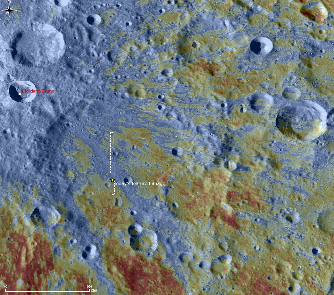
Can we afford NOT to? Resource map of the north pole of the Moon [from Spudis and Lavoie, in press].

Paul D. Spudis
The Once & Future Moon
Smithsonian Air & Space

We are almost at the end of a year that has seen major changes in our space program. We have in hand a report from a “blue ribbon” Presidential committee that concluded that Project Constellation, the architecture NASA had chosen to implement the Vision for Space Exploration, was not affordable at current funding levels but might be accomplished with an increase in the agency’s budget, on the order of an additional $3 billion per year. The committee presented architectural alternatives to Project Constellation, one of which eliminated the Moon in favor of a “flexible path” that allowed human missions to other destinations (e.g., an L-point, an asteroid) beyond low Earth orbit.

I take issue with several points in the Augustine report and have commented on them at length in several previous posts of this blog. But now that the dust has settled and we have a “new direction” for our space program, its two principal deficiencies are evident. First, by discarding the clear strategic direction provided by the VSE, we have entered an era of uncertainty and aimlessness of purpose in our space program. This institutional drift is reflected in nearly daily stories about NASA – new missions studies, new launch vehicles, the endless personal backbiting amongst the space internet cognoscenti. Second, the assertion of the report that return to the Moon is “unaffordable” is simply wrong. How you go to the Moon and what your mission is there determines cost and all the committee looked at were cost models for the existing program and minor variants on it.

I have made both of these points here and elsewhere and many were quick to challenge me to show how we could go back to the Moon under the conditions and assumptions of the Augustine committee. Rather than shut up, I now put up. I have submitted a paper for publication in the Proceedings of Space Manufacturing 14, the conference in late October sponsored by the Space Studies Institute. My co-author Tony Lavoie and I have developed an architecture that returns America to the Moon with a specific mission in an affordable way. Our paper has now been accepted for publication, so I am posting a pre-print of it on my web site and will summarize our findings here.

One of the biggest problems with NASA’s implementation of the VSE was that they never understood why we were going to the Moon. I base this assertion on their own statements, actions and publications. Early workshops were held by the agency to develop a rationale for lunar return. The Exploration Directorate issued a poster showing six “themes” for lunar return, but no one at the agency could state their mission in one sentence. At a Congressional hearing in 2009, the acting administrator of NASA said the he did not understand what “return to the Moon” meant in terms of mission objectives and activities.

The agency took the position that they were merely transportation agents – that it was up to the various “user” communities to decide that activities were to be undertaken on the Moon. As a matter of fact, the Vision itself very specifically laid out what was to be done on the Moon and even how to approach it. The purpose of lunar return is to learn the skills and develop the technologies we need to live on another world. The Vision specifically mentions that one skill we need to acquire is the use of extraterrestrial resources to make both exploration and human presence permanent and sustainable.

NASA ignored this direction. There are many reasons why they did this, but I believe that the main one was they did not know how to create sustainable human presence on the Moon using its resources and were concerned that such a thing might not be possible. But building large rockets is certainly possible – history documented that. So the VSE morphed into a rocket-building program, an Apollo Redux because that’s what the agency (allegedly) knew how to do. The only problem was that we do not live in the Apollo era and the space program no longer gets 7% of the federal budget.

The approach we take in our new architecture is to: 1) define the mission clearly and directly; and 2) design an architecture that accomplishes the mission in small, incremental and cumulative steps. These last three adjectives are important: Steps must be small to be affordable, not only under existing budgetary constraints but also under possible lower budgets that could be necessitated by national economic conditions in the future. The steps should be incremental, meaning that each step adds some asset or capability and must work in tandem with previous equipment and operations. Finally, the steps must interlock such that the whole is greater than the sum of the parts. The architecture cumulatively increases features and capabilities with time.

We take as our mission the original Vision for Space Exploration. We go to the Moon to establish a permanent human presence there and a reusable, refuelable, and extensible transportation system to support such presence. Once established, we will have a space faring system that can not only routinely access the Moon, but all other points in cislunar space and beyond, including the L-points and near-Earth asteroids.

How do we accomplish all this? One of the principal advantages of the Moon as our first goal beyond LEO is that: 1) it has the material and energy resources we need; and 2) it is both close and accessible. This latter set of attributes is more important than you might think. The closeness of the Moon allows us to directly control and operate robots on the lunar surface; the time-lag between action on Earth and execution on the Moon is only a bit over one second. We can operate machines on the Moon in near real-time. Additionally, we can send space vehicles to the Moon at virtually any time. No other space destination is so easily and readily accessible.

The key to making all this work is the use of teleoperated robotic machines. We go to the Moon robotically first and later with people. These robots are controlled by people on the Earth. They prospect for resources, test techniques, evaluate product yields, set up processing plants, and begin harvesting lunar resources almost immediately. The extracted products are cached on the surface for future use. The entire lunar outpost is set-up and made operational by these robotic machines.

Our architecture is designed so that time is a free variable. We make constant, steady progress toward our goal; in fiscally lean times, we go slower, but we can accelerate the schedule if more money is available. Making individual steps small and incremental permits this approach – we are not waiting for the development or advent of some “magic carpet” piece of equipment to fill a major hole in our plan.

So what’s the bottom line? Our plan creates a fully functional, operating lunar resource outpost capable of manufacturing 150 metric tonnes of water per year. In addition, we develop a reusable space faring system, one fueled by lunar propellant and expandable to support missions to the planets and destinations throughout cislunar space. We do all of this under the budget guidelines provided to the Augustine committee by NASA; total aggregate funding for this program is less than $88 billion (real-year dollars), with peak funding of $7.1 B in Year 11. Although schedule is flexible, we achieve our primary mission goals by the end of year 16. We have had our assumptions, mass estimates and costing examined, reviewed and validated by a variety of space experts, including the Engineering Directorate Mission Analysis Group at NASA’s Marshall Space Flight Center. This program architecture does what Project Constellation did not: it returns America to the Moon with a legacy of real and permanent space faring infrastructure.

In contrast to the current drift of our space program, the original Vision for Space Exploration set a strategic direction and path that made sense, giving us an expanding sphere of human reach beyond low Earth orbit. The idea that America cannot afford space is ludicrous – we have the world’s largest economy and the amount we spend on space is now less than one-half of one percent of the federal budget. But whatever we spend on space, we should expect to get something in return. A lunar outpost and space transportation system gives us a return on our investment; a program of one-off, stunt missions does not.

The path forward into the future is still open to us.

Friday, December 17, 2010

Serene Solstice Shadows

LRO's unprecedented topography of the Moon


The rugged South Pole, revealed through LOLA's millions of laser hits centered on prominent (if small, at only 10 kilometers) Shackleton. The jagged ancient rim of South Pole-Aitken (SPA) Basin, it's smaller near side component to the north of Malapert (center top) and the fantastically high Liebnitz beta massifs. To their left Cabeus hides the highest concentrations of water while some of the other permanently-shadowed areas do and others mysteriously do not hold such promise [NASA/GSFC/MIT/SVS].

Nancy N. Jones
Goddard Space Flight Center

NASA's Lunar Reconnaissance Orbiter is allowing researchers to create the most precise and complete map to date of the moon's complex, heavily cratered landscape.


LOLA topographic map centered on the Apollo 15 landing site, highlighting the Apennine and Caucasus ranges and the fairly subtle wrinkling in Serenitatis. The false colors indicate elevation: red areas are highest and blue lowest [NASA/GSFC/MIT/SVS].

"This dataset is being used to make digital elevation and terrain maps that will be a fundamental reference for future scientific and human exploration missions to the moon," said Dr. Gregory Neumann of NASA's Goddard Space Flight Center in Greenbelt, Md. "After about one year taking data, we already have nearly 3 billion data points from the Lunar Orbiter Laser Altimeter on board the LRO spacecraft, with near-uniform longitudinal coverage. We expect to continue to make measurements at this rate through the next two years of the science phase of the mission and beyond. Near the poles, we expect to provide near-GPS-like navigational capability as coverage is denser due to the spacecraft's polar orbit." Neumann will present the map at the American Geophysical Union meeting in San Francisco December 17.

The Lunar Orbiter Laser Altimeter (LOLA) works by propagating a single laser pulse through a Diffractive Optical Element that splits it into five beams. These beams then strike and are backscattered from the lunar surface. From the return pulse, the LOLA electronics determines the time of flight which, accounting for the speed of light, provides a precise measurement of the range from the spacecraft to the lunar surface. Range measurements, combined with accurate tracking of the spacecraft's location, are used to build a map revealing the contours of the lunar landscape. The five beams create a two-dimensional spot pattern that unambiguously reveals slopes. LOLA will also measure the spreading of the return pulse to get the surface roughness and the change in the transmitted compared to the return energy of the pulse to determine surface reflectance.


The "resource-rich" lunar North, triangulated by Hermite on the right, where the Solar System's coldest temperatures have been recorded, wide-spread Rozhdestvenskiy across the top and Perry, bottom right, hugging the North Pole along with recently-designated Whipple [NASA/GSFC/MIT/SVS].

The new LOLA maps are more accurate and sample more places on the lunar surface than any available before. "The positional errors of image mosaics of the lunar far side, where direct spacecraft tracking – the most accurate -- is unavailable, have been one to ten kilometers (about 0.62 to 6.2 miles)," said Neumann. "We're beating these down to the level of 30 meters (almost 100 feet) or less spatially and one meter (almost 3.3 feet) vertically. At the poles, where illumination rarely provides more than a glimpse of the topography below the crater peaks, we found systematic horizontal errors of hundreds of meters (hundreds of yards) as well." In terms of coverage, the nearly three billion range measurements so far by LRO compare to about eight million to nine million each from three recent international lunar missions, according to Neumann. "They were limited to a mile or so between individual data points, whereas our measurements are spaced about 57 meters (about 187 feet) apart in five adjacent tracks separated by about 15 meters (almost 50 feet)."

"Recent papers have clarified some aspects of lunar processes based solely on the more precise topography provided by the new LOLA maps," adds Neumann, "such as lunar crater density and resurfacing by impacts, or the formation of multi-ring basins."

"The LOLA data also allow us to define the current and historical illumination environment on the moon," said Neumann. Lunar illumination history is important for discovering areas that have been shaded for long periods. Such places, typically in deep craters near the lunar poles, act like cold storage, and are capable of accumulating and preserving volatile material like water ice.

The landscape in polar craters is mysterious because their depths are often in shadow. The new LOLA dataset is illuminating details of their topography for the first time. "Until LRO and the recent Japanese Kaguya mission, we had no idea of what the extremes of polar crater slopes were," said Neumann. "Now, we find slopes of 36 degrees over several kilometers (several thousands of yards) in Shackleton crater, for example, which would make traverses quite difficult and apparently causes landslides. The LOLA measurements of shadowed polar crater slopes and their surface roughness take place at scales from lander size to kilometers. These measurements are helping the LRO science team model the thermal environment of these craters, and team members are developing temperature maps of them."

LRO and LOLA were built and are managed by NASA Goddard. The research was funded by NASA's Exploration Systems Mission Directorate at NASA Headquarters in Washington.

Thursday, December 16, 2010

Chang'e-1 maps Moon's Helium-3 inventory


An interpolation of the total amount of Helium-3 per square meter "fixed" in the lunar regolith (ppb/m2), from "Global inventory of Helium-3 in lunar regoliths estimated by a multi-channel microwave radiometer on the Chang-E 1 lunar satellite," F. WenZhe, et al., Chinese Science Bulletin, December 2010, Vol. LV, No.35. Scarce on Earth, Helium-3 is a strategic ionized element and projected future source of clean energy. Likely a bi-product of solar incidence, as interesting as it's interpolated abundance in nearside mares Tranquillitatis, Fecunditatis and Oceanus Procellarum is it's apparent lack in similar landscapes. While the methods used to indirectly locate and map Helium-3 on the Moon is not new, the study may be of the highest resolution ever publicly released, Point HERE for a full-resolution view [Fudan University/Institut de Physique du Globe de Paris].

Fa WenZhe & Jin YaQiu
Fudan University &
Institut de Physique du Globe de Paris


Helium-3 (3He) implanted by solar wind in the lunar regolith is a valuable resource because of its potential as a fusion fuel. On the basis of the Apollo regolith samples, a linear relationship between 3He abundance and solar wind flux, optical maturity and TiO2 content has been presented. China successfully launched its first lunar exploration satellite Chang-E 1 (CE-1) on October 24, 2007. A multi-channeled microwave radiometer was aboard the satellite with the purpose of measuring microwave thermal emission from the lunar surface layer. From the multi-channel brightness temperature (Tb) observed by CE-1, the global distribution of the regolith thickness was inverted from the multi-channel Tb, and was used to evaluate the total amount of 3He per unit area in the lunar regolith. The global inventory of 3He was estimated as being 6.6×10⁸ kg; 3.7×10⁸ kg for the lunar nearside and 2.9×10⁸ kg for the lunar farside.

Helium-3 (3He) is a clean, safe and non-radioactive fusion fuel. Compared with traditional fusion reaction of using 3H, the reaction involving 3He does not generate any high-energy neutrons and does not produce prolonged radioactivity, and hence is not dangerous to a reactor or the environment.

Terrestrial sources of 3He are extremely rare and the total inventory is only about 2.0×10⁴ kg. Because there is neither a geomagnetic field nor an atmosphere on the Moon, solar wind particles can impinge directly upon the lunar surface and hence be captured by lunar regolith particles. As a consequence, a significant amount of solar wind elements (such as helium) have accumulated in the regolith during the long geological history of the Moon.

Significant work has been done to estimate the 3He implantation and abundance in the lunar regolith during the last few decades, based on the returned regolith samples from the Apollo and Luna missions. However, there has been a need to have a precise lunar regolith thickness distribution map of the whole lunar surface to determine the quantities of 3He present.

China successfully launched its first lunar exploration satellite Chang-E 1 (CE-1) on October 24, 2007. A multichannel microwave radiometer was aboard the satellite and had the purpose of measuring microwave thermal emissions from the lunar surface layer. From the analysis of the primary CE-1 observations, consisting of the brightness temperature (Tb) (from November 2007 to February 2008), Fa and Jin successfully inverted the global distribution of regolith thickness. This newly acquired dataset provided an opportunity to quantitatively estimate the global inventory of the 3He accumulated in the whole regolith.

In this study, by combining the models of normalized solar wind flux over the lunar surface, the global distribution of TiO2 content and the surface optical maturity derived from Clementine UVVIS multi-spectral data, a linear relationship between 3He abundance, TiO2 content and surface optical maturity can be derived for the global distribution of 3He in the lunar near-surface layer (thickness less than 1 μm). Using the newly acquired global distribution of the regolith thickness obtained from CE-1 multi-channel radiometer observations, the total amount of 3He per unit area in lunar regolith can then be obtained.

Read the Study, HERE.

Monday, December 13, 2010

The Pioneer lunar orbiters: a forgotten failure


STL (TRW) - built Able-4 and 5 lunar orbiters were the most advanced American spacecraft of their time, part of the ARPA-sponsored Operation Mona, which was approved by President Eisenhower on March 27, 1958 [NASA].

Andrew J. LaPage
The Space Review

There has been a resurgence in interest in the exploration of the Moon. In addition to current American efforts, Japan, India, and China have placed spacecraft into orbit around the Moon in recent years and they have plans to land on the lunar surface in the future. A genuine competition between the Asian space powers is developing to exploit the Moon and its resources. The success of these programs owes much to the experience gained during the competition between the Soviet Union and the United States a half a century ago in the opening years of the Space Age.

Before NASA was founded on October 1, 1958, the US Air Force had ambitious plans for space exploration. During the national debate that followed the launch of Sputnik, the Air Force was trying to position itself so that it could dominate the nation’s infant space program. Even after the Advanced Research Projects Agency (ARPA) was founded in February of 1958 and was given the task of coordinating America’s military space programs, Air Force efforts and plans figured prominently.
By the fall of 1959, the Able combination along with its cousin, the Vanguard upper stages, had an abysmal performance record.
The Air Force’s first step beyond Earth orbit, called Project Able, was a series of attempts to place a small spacecraft into orbit around the Moon. These orbiters, along with a pair of small US Army-JPL lunar flyby probes, were part of the ARPA-sponsored Operation Mona, which was approved by President Dwight Eisenhower on March 27, 1958. Three launch attempts made by the Air Force between August and November of 1958, now called Pioneers 0, 1, and 2; all failed to reach the Moon. But even before these missions flew, the Air Force, in conjunction with the builders of their first lunar orbiters, STL (Space Technology Laboratory, a division of TRW), began to study follow-on missions not only to lunar orbit but also to Venus, given priority. Little was known about Earth’s near twin at this time and many believed Venus ranked with Mars as a likely abode for extraterrestrial life, making it a desirable target for exploration.

Read the article, HERE.

Friday, December 10, 2010

Impact melt features of Tycho's floor


Depressions and positive relief features characteristic of the floor of Tycho were caused by a complex stew of granular material and impact melt cooling and settling to the floor. Image field of view is 370 meters. LROC NAC M119923147L [NASA/GSFC/Arizona State University].

Drew Enns
LROC News System

Impact melt creates a wide variety of features on the Moon. These include melt ponds, draped ejecta, viscous flows, linear and nonlinear depressions, and positive relief features. As impact melts mix with loose rock during crater formation, solid pieces of rock stick above the surface of the ponding melt to form little peaks (positive relief features). The depressions are possibly cooling fractures in the melt that result as the melt slowly solidifies and contracts (the opposite of how water behaves when it freezes), however they could also be part of an impact melt drainage network. We don't know for certain know the origin of all of these features, the best way to find out is to have astronauts traverse this terrain while exploring the Moon.


LROC WAC mosaic with arrow noting the location of the melt features within Tycho crater seen in the NAC image above. Image width is 150 km [NASA/GSFC/Arizona State University].

Can you find more impact melt features in the NAC frame?


Kilometer-wide context for the full-resolution Featured Image above, a wider looks at the 2.8 km-wide LROC Narrow Angle Camera observation highlighted above, LROC NAC M119923147LE, LRO orbit 2806, February 4, 2010 [NASA/GSFC/Arizona State University].


The LROC Wide Angle Camera mosaic affixed to the lunar digital elevation model available to users of Google Earth provides some scale and the illusion of perspective, seen here showing Tycho's interior, between the slumped northeastern interior rim and central peak, looking North [NASA/JAXA/SELENE/USGS/GSFC/Google/Arizona State University].

Related Posts:
The Floor of Tycho - Constellation ROI

Thursday, December 9, 2010

Ejecta on the slumped inner wall of Tycho


Halfway down the inner wall of 109 million year old Tycho, an otherwise average crater for its size prominent as seen from Earth because of its hemisphere-wide ejecta rays composed of "optically immature" reflective materials - a 320 meter block of ejecta covered with a veneer of impact melt. Image field of view is 370 meters, LROC Narrow Angle Camera observation M142334392RE [NASA/GFSC/Arizona State University].

Drew Enns
LROC News System

Tycho crater is a Copernican age crater (85 km diameter - 43.3°S, 348.8°E). It is named for the 16th century Danish astronomer Tycho Brahe and is one of the most visible features on the near side of the Moon. Its ray system is so obvious and widespread that Apollo 17 astronauts sampled its ejecta, over 2000 km away from the crater! Scientists dated the Tycho samples at ~ 110 million years. We also have surface views of Tycho's ejecta blanket gathered using the Surveyor 7 soft lander.


LROC Wide Angle Camera context mosaic of Tycho with an arrow pointing to the ejecta block above. (Image field of view is 150 kilometers) The landing site of Surveyor 7 (1968) is near the top-center edge [NASA/GFSC/Arizona State University].

Notice the smooth areas on the top of the ejecta block in this NAC frame. Most likely the smooth area is a thin sheet of impact melt. The large block was probably flung up during the impact event, fell back down into the crater, and subsequently covered by impact melt. This series of events must have occurred quickly after the impact, as the melt would solidify soon after forming.

Explore the impact melt within Tycho's inner walls in the full LROC NAC image.

Related Posts:
Impact melt at Necho crater
Natural Bridge on the Moon


Northeastern interior of Tycho from Japan's spectacular "fly-over" video (2008) from data assembled using the Terrain Camera on-board SELENE-1 ("Kaguya"). The ejecta block and melt views further up by the LROC NAC rests amidst thousands of similarly-sized features on the slumped inner wall terrace near upper right center. [JAXA/SELENE].

Monday, December 6, 2010

The Space Review: Apollo secrets & whispers


Illustration of an Apollo Command & Service Module docked to the NRO Lunar Mapping and Survey System [Space Review/G. de Chiara].

Dwayne A. Day
The Space Review

During the 1960s, the existence of the National Reconnaissance Office (NRO), which managed America’s spy satellite programs, was highly secret. It is difficult to understand why this was so, but the ability to use powerful satellites to peer down into the Soviet Union, count strategic weapons systems, and determine what the Soviets were doing was highly valuable and therefore prized. Although the Soviet government and the American public knew that the United States was launching satellites into orbit to conduct espionage, US government officials felt that even admitting that these activities were being conducted would attract more attention to them, and possibly encourage the Soviets to start shooting at them in peacetime (everybody expected them to shoot at American satellites in wartime). This intense secrecy is the main reason why the revelation that the NRO made then-current, highly-capable reconnaissance satellite technology available to NASA for the Apollo program is so surprising.
The existence of the Lunar Mapping and Survey System was not classified, and actually appeared in an open source publication, a space encyclopedia aimed at kids that was produced in the later 1960s.
As revealed by Vance Mitchell in the current issue of Quest, and discussed here last week (see “Black Apollo”, The Space Review, November 29, 2010), beginning in 1964 the NRO and NASA collaborated to allow NASA to use a modified KH-7 GAMBIT reconnaissance satellite on manned Apollo missions to photograph potential lunar landing sites. These missions were planned to occur in the event that the robotic Lunar Orbiter photographs were insufficient to determine if it was safe enough for an astronaut to land a Lunar Module on the surface. The KH-7 was then one of the two primary American reconnaissance satellites in service. NASA soon employed contractors Lockheed, General Electric, and Kodak to begin work on what was known as the Lunar Mapping and Survey System, or LM&SS. Details of the plan remain sketchy, but parts of hardware for four cameras were constructed before the program was canceled in summer 1967, after NASA determined that the Lunar Orbiter photographs were good enough to pick safe landing sites.

Read the full article, HERE.

Friday, December 3, 2010

Rilles as far as the eye can see at Prinz


LROC Wide Angle Camera (WAC) mosaic of the rille-rich Prinz crater region, east of Aristarchus Plateau. Bench-like features are visible in the Prinz B depression and two flows originating in Prinz B converge just west of the arrow [NASA/GSFC/Arizona State University].


The bouldery, higher-reflectance mound in the central portion of this image is an island near the source region, Prinz B, for a short sinuous rille. The two rilles join at the triangular tip of this kipuka-like structure and flow northwestward for ~10 km. Image field of view is 500 meters [NASA/GSFC/Arizona State University].


Backing away for a full-width view of LROC Narrow Angle Camera observation M135473387RE, LRO orbit 5098, August 3, 2010, res. 0.5 m. The images highlight a fork on the western edge of Prinz B, a source depression for an unnamed rille. Image field of view is 2.5 kilometers [NASA/GSFC/Arizona State University].

Lillian Ostrach
LROC News Service

Virtually traverse the Prinz region of the Moon in the 100 m/pixel LROC WAC mosaic and explore the Prinz B rilles joining in the full LROC NAC frame!


The dramatic morphology of the Prinz-Harbinger region is usually overshadowed by bright Aristarchus to its west (upper right), seen here fastened to the lunar frame available to users of Google Earth (v.6). The region's features are best seen at local sunrise or sunset since the relief reflects little differences in elevation. The ridge at right averages only 300 meters higher than the depths within nearby rilles [NASA/USGS/JAXA/SELENE/GSFC/Google/Arizona State University].

Related posts
Rimae Prinz Region - Constellation ROI
Rimae Posidonius
Secrets of Schröteri

Thursday, December 2, 2010

Secrets of Schröteri


Vallis Schröteri is a magnificent sinuous rille and of particular interest is its inner rille, which diverges from the primary rille near the arrow. This nested form indicates that multiple eruptive events occurred or there was a large change in the volume of a single eruption over time. LROC WAC mosaic, 100 m/pixel [NASA/GSFC/Arizona State University].


LROC NAC close-up of a bend in the inner rille of Vallis Schröteri; the rille walls are visible in the upper left and lower right corners of this image. The arrow in the LROC WAC mosaic denotes the location of this image; field of view is 600 meters [NASA/GSFC/Arizona State University].

Lillian Ostrach

LROC News System

Explore the largest rille on the Moon in the LROC WAC mosaic and the LROC NAC full image! Compare the sinuous nature of these rilles to yesterday's Featured Image of Rimae Posidonius - what features are similar and what is different?


Backing off from the LROC Narrow Angle Camera close-up slicing through Vallis Schröteri, geologically fascinating because not only is it the largest lunar sinuous rille, it is also composed of a primary rille and a smaller, inner rille. Full LROC Image field of view is 1.5 km [NASA/GSFC/Arizona State University].


Three views of the Aristarchus Plateau "chevron," lording over the vast Oceanus Procellarum. At bottom, from 2008, a 200 kilometer-wide (at bottom) SELENE-1 (Kaguya) HDTV view of the Aristarchus Plateau that is close to it's true optical appearance from orbit, according to those who have actually been there. The subtleties of the variety of actual color variation here are difficult to detect at first glance, though they are definitely present [JAXA/NHK/SELENE].

No matter how often the Aristarchus Plateau is imaged, and we have presented a wide variety of such images here, as seen in different wavelengths and bands from Earth and from lunar orbit, every new opportunity seems to show a new face to this feature, unique in our star system. Above the Kaguya HDTV still shows two perspectives of the LROC Wide Angle Camera mosaic attached to the digital elevation model of the Moon available in Google Earth. Besides the valley, where details are obscured in these greatly reduced images, is the crater Herodotus, the far older sister of Aristarchus.


Related posts:
Aristarchus Plateau 1: Amazing Geologic Diversity
Rille within a rille!
The Great Wall of Aristarchus
The colorful Moon
LROC: Aristarchus - Up from the Depths
LOLA's Aristarchus Plateau

Wednesday, December 1, 2010

Rimae Posidonius


Spanning over 130 km in length, Rimae Posidonius is a sinuous rille winding across the floor of Posidonius crater. This LROC Wide Angle Camera (WAC) mosaic (at 100 m/pixel) is seen here wedded to the lunar digital elevation model (DEM) available to users of the Google Earth application (>v.5). The arrow points to the rille and location of the accompanying LROC Narrow Angle Camera (NAC) close-up below - from LROC Featured Image, December 1, 2010 [NASA/GSFC/Arizona State University].

Lillian Ostrach
LROC News System

Sinuous rilles are remarkable features resulting from turbulent flow of low viscosity (very fluid), high temperature lavas that erodes the pre-existing surface. In turbulent fluid flows, eddies and vortices form that can be highly erosive and result in the twists and turns seen in many rilles. This rille, located on the western edge of Posidonius crater (~100 km diameter, floor-fractured and partially mare-filled), tightly winds against the northern crater wall and then veers away in a southerly course.


LROC Narrow Angle Camera close-up view of boulders, derived from the mare lavas that flooded the crater, outcropping from the eastern rille wall. The rille itself runs on the left of the shedding rock. LROC NAC observation M113771795R, LRO orbit 1900, November 25, 2009; field of view above is 500 meters [NASA/GSFC/Arizona State University].

Why are scientists captivated by sinuous rilles? Part of the reason is purely aesthetic - each sinuous rille is different. Some sinuous rilles are less curvy, some - like Rimae Posidonius - look like squiggles, while yet other rilles are so windy that they have horseshoe-shaped curves. Scientifically, however, sinuous rilles are exciting because it's possible to see layers of mare lavas that were cut through during the rille formation - as long as the regolith slumping down the walls isn't thick enough to obscure them! Besides exposing layers in the lava flows, rilles also give you an almost dynamic look at where lava flowed, suggesting very high effusion rates over long periods of time (often much higher than typical of those on Earth). Some rilles are believed to contain pyroclastics, which can tell scientists something about the volcanic history of the rille. Sinuous rilles in the Rimae Prinz region of the Moon may even host a lava tube network; lava tubes may be instrumental in future human exploration activities.

What do you think is most scientifically fascinating about sinuous rilles? Discover the winding turns of this sinuous rille in the LROC WAC mosaic and in the full LROC NAC image!

Related posts:
Marius Hills
Aristarchus Plateau 1: Amazing Geologic Diversity
Rille within a rille!


HDTV still from Japan's SELENE-1 (Kaguya) in 2008 shows Posidonius and Rimae Posidonius in natural color, but without much more clarity than what can regularly be imaged of this area on the northeastern edge of Mare Serenitatis from Earth. Nevertheless, the Kaguya mission provided unparalleled science along with views of the Moon previously available only to Apollo's astronauts, along with original views never seen before, like the permanently shadowed interior of Shackleton crater at the Moon's south pole [JAXA/NHK/SELENE].

Wednesday, November 24, 2010

Erosional troughs on crater wall


An erosional trough (400 meters long x 100 to 200 meters wide) represents a significant chunk of material slipped down the steep upper inside east wall of the notably bright farside crater Moore F. Morphologically it resembles a martian sapping feature, suggested as the result of erosion by water flowing and undermining the subsurface. LROC Narrow Angle Camera observation M128075293R, LRO orbit 4008, May 9, 2010, Field of view is 500 meters, with the Sun from the southwest at lower right [NASA/GSFC/Arizona State University].

Jeff Plescia
LROC News System

A number of erosional troughs are observed on the inner wall of Moore F on the lunar far side (37.21°N, 185.48°E). The crater is 23.7 km in diameter and is relatively fresh, as evidenced by bright ejecta and its pristine morphology. Numerous troughs are observed extending down the inner crater wall. The feature shown here is the freshest with a smooth floor composed of bright material.

The trough is about 810 meters long and around 140 meters wide near its head, narrowing slightly to about 105 m in the middle before widening to some 200 meters.


Several other older troughs occur along the crater wall to the north and south of this feature. They all appear to begin at about the same level of the crater wall, an area marked by what appears to be discontinuous outcrops of bedrock. The older features are darker, with an albedo similar to the surrounding terrain, as opposed to this feature, which has a considerably higher albedo.

These features resemble so-called sapping features observed on Mars. The martian features are suggested to be formed by the release of ground-water along a cliff face causing headward erosion of the trough. In these lunar examples, it is highly unlikely that ground water occurs. Presumably the features are the result of dry debris flows of fine-grained, unstable material. Once mobilized, the dry granular flow broadened into a fan-shaped deposit. Here the material extends more than a kilometer downslope from the mouth of the trough.

Explore the full NAC image.

Check out a related post!

Monday, November 22, 2010

Delicate patterns in Giordano Bruno ejecta


Pan of the LROC Featured Image released November 22, 2010 - Narrow Angle Camera (NAC) view of the "Far edge of the Giordano Bruno crater ejecta blanket." LROC NAC observation M115617436L, LRO orbit 2172, December 16, 2009; resolution 0.9 m/pixel, image field of view is 1.08 kilometer, the Sun's illumination is from the right. See the full-size original LROC Featured Image HERE. The famous young crater Giordano Bruno is to the northwest [NASA/GSFC/Arizona State University].

Hiroyuki Sato
LROC News System

Impact cratering is a common and universal phenomena on every planet and satellite. However, we still do not completely understand this complicated process. The Moon is one of the best libraries of impact craters in our Solar System because its surface is not modified by atmospheric weathering or water erosion. The dominant form of erosion on the Moon is indeed impact cratering.


Full resolution (86 centimeters per pixel) close-up of LROC NAC observation M115617436L showing how the Giordano Bruno ejecta blanket scoured and partially erased the terrain it channeled and buried. The pattern is reminiscent of the "elephant skin" pattern characteristic of nearly all older lunar surfaces higher than surrounding elevations [NASA/GSFC/Arizona State University].

Today's featured image shows the edge of the Giordano Bruno crater ejecta (35.94°N, 102.91°E); upper-left of the WAC image (below). Here you can easily see the delicate patterns of ejecta overlying pre-existing terrain. The ejecta pattern points back to the crater, and gives the impression of a fast moving surface flow. Combining the morphology of the ejecta, and new topographic data from NAC stereo pairs, scientists will be better equipped to unravel the physics of ejecta emplacement.


Context map around Giordano Bruno crater (centered 107°E, 34°N). LROC WAC 100 m/p monochrome mosaic overlayed by optical maturity (OMAT) parameter [Lucey et al, 2000], generated from Clementine Ultra-Violet/Visible wavelength (UVVIS) data, at 200 m/p. Blue corresponds to younger, "optically immature" material, and red is an older and more mature surface. The white dashed box corresponds to the footprint of the full LROC NAC observation from which the LROC Featured Image released November 22, 2010 was taken . See the full-resolution original of the above HERE [NASA/GSFC/Arizona State University].


Zooming in upon Giordano Bruno, using the LROC Planetary Data Base (PDS) Image Search interface now vastly improved with the new Wide Angle Camera (WAC) global mosaics, quickly unveils the brighter low OMAT influence the young crater's impact event has had on its surroundings, just beyond line-of-sight view from Earth past the Moon's eastern limb [NASA/GSFC/Arizona State University].

Explore the Giordano Bruno ejecta blanket NAC frame!

Reference: Lucey et al. (2000) JGR, v105, no. E8, p.20377-20386.

Previous post showing the floor of Giordano Bruno.

Thursday, November 18, 2010

Avalanche in Robinson crater


Northern slope inside Robinson crater, far to the northeast on the face of a Full Moon as seen from Earth (59.1°N, 314.1°E). Close-up from LROC Narrow Angle Camera observation M114259768R, LRO orbit 1972, November 30, 2009 Image resolution is 0.52 m/pixel, field og view 620 meters, sun light is from right, and the slope runs from top to bottom. View the full-width Featured Image, HERE [NASA/GSFC/Arizona State University].

Hiroyuki Sato
LROC News System

An impact crater changes its shape with time by various degradation processes, such as wall slumping, infilling with ejecta deposits from nearby impacts, and volcanic activities. Rock avalanches as shown in today's featured image also contribute to modifying crater shape little by little.


Pulling back from the NAC observation and this view inside Robinson north rim show wispy fine debris trails [NASA/GSFC/Arizona State University].

Multiple tongue shaped flow fronts in this image evoke liquid (Newtonian) flow features, especially mudflows. Similar features have been found on Mars, and are interpreted to represent recent mudflows. Water is not stable on the Moon's surface (except perhaps as ice in permanently shadowed craters), so these flows are dry (granular) rock slides. Perhaps some of the flow features on Mars thought to indicate wet mudflows are really dry granular flows?


Context map of Robinson crater, centered near 59.1°N, 314.0°E. LROC Wide Angle Camera 100 m/px monochrome global mosaic overlayed by the WAC color Digital Terrain Model (DTM) at a resolution of 500 meters/px. The blue rectangle outlines the full footprint of the LROC team's Featured NAC Image November 18, 2010. View the full field of view in the original release, HERE [NASA/GSFC/Arizona State University].


A wider view showing the location of the rockslide just inside the northern rim of Robinson, in the context of the landmark Imbrium impact event. The vicinity of Robinson, near the long and winding Mare Frigoris, appears to be on a battered outer ring of Imbrium [NASA/LROC PDS Interface].

Explore lunar landslides by viewing the full NAC frame!

Similar slides can be seen in a small crater in the center of crater Henry Frères.

Tuesday, November 16, 2010

Slope failure near Aratus


Northern flank of cone-shaped mound north of Aratus crater (23.68°N, 4.50°E) in the rough badlands west of Mare Serenitatis. LROC Narrow Angle Camera M117461002L, LRO orbit 2444, January 6, 2010. Image field of view is about 672 meters. Illumination is from west-southwest (left) at an incidence angle of 83° and downslope direction is from bottom to top. Click HERE for the full-size release. [NASA/GSFC/Arizona State University].

Hiroyuki Sato
LROC News System

The featured image above displays a mixture of smooth (denoted "S") bumpy (B) and rough textured (R) surfaces. Some of the bumpy-textured material is enclosed by the rough-textured material. The downhill-side edges of the smooth areas are scalloped and are often accompanied by parallel wrinkles.


LROC Wide Angle Camera (WAC) monochrome mosaic shows it's relation to Hadley Valley, the steep mountains bordering Palus Putredinis and the July 1971 landing site of Apollo 15 (76 kilometers away) - LROC PDS Image Search Interface [NASA/GSFC/Arizona State University].

The uphill edges of each piece of smooth-textured surface appear to have separated from the smooth material up-slope from them, leaving a gap of rough surfaced material. It is possible that these characteristics indicate slope failure (landslide) of an upper thin layer, similar to what we see on terrestrial landslides or a snow avalanche. This type of sliding occurs where the material strengths of upper and subsurface layers have large contrast, typically unconsolidated material overlaying a more rigid substrate.

Estimates of sliding layer thickness, local topography, and morphological characterization of flow features allow scientists to determine the geotechnical (soil mechanics) properties of the lunar regolith. Such studies are key to designing future rovers, space suits, and tools for exploring the Moon.


Topographic context map of the vicinity of Aratus (centered near 23.09°N, 4.43°E). LROC Wide Angle Camera 100 m/p resolution monochrome mosaic overlayed with the WAC color Digital Terrain Model (DTM, 500 m/p). (Click HERE to view the full-size original.) Blue-dashed rectangle corresponds to the footprint of the full LROC frame from which the LROC featured image of November 16, 2010 was cropped [NASA/GSFC/Arizona State University].

Explore lunar landslides by viewing the full NAC frame.

Friday, November 12, 2010

The Central Peak of Kepler


Boulders and simple craters perched on top of Kepler crater's central peak. LROC Narrow Angle Camera (NAC) observation M111843702R, LRO orbit 1616, November 2, 2009; field of view (below and HERE) is 500 meters [NASA/GSFC/Arizona State University].


Drew Enns
LROC News Service

There are two basic types of impact craters: simple and complex. Simple craters form a bowl-like rimmed depression, and complex craters (such as Kepler) display central peaks, terraces, and flat floors. Complex craters occur above a certain diameter crater, the cutoff diameter is dependent on gravity, so it varies from planet to planet (or moon to moon). On the Moon the size cutoff between simple and complex craters is between 10 and 20 km, on the Earth it is between 2 and 5 km.


A full-sized segment of an Apollo 12 orbital shot featured in previous postings from Drew Enns discussing Kepler. From this foreshortened angle (see context below) it's easier to see the minimal central peak does not exceed the crater's rim in elevation [NASA/LPI].


An LROC Wide Angle Camera mosaic of Kepler with an arrow indicating the location of featured NAC image above can be viewed HERE.

Despite the label "central peak," a central peak is not always exactly in the center of a crater, nor is it always symmetrically shaped; Kepler crater is an example. Instead of having a nice central peak, Kepler crater has an irregular off-center peak. This form is most likely due to the crater being close to the boundary diameter between a simple and complex crater. Larger craters, such as King crater, can also display oddly shaped central peaks that are likely the result of an oblique impact.
Link
Browse the whole NAC image of Kepler crater and inspect the landforms associated with its central peak. Can you find evidence of impact melt on the central peak, terraces, and floor?

Related Posts:
Concentric crater
Kepler Crater Ejecta
Kepler's Rim