Thursday, June 27, 2013

Rima Marius Layering

Basalt layering, a slice through the floor of Oceanus Procellarum, is visible along the wall of this section of Rima Marius. LROC Narrow Angle Camera (NAC) Extended Science Mission observation M1103881010R, LRO orbit 14991, October 3, 2012; 21.88° angle of incidence over a 1.3 km-wide field of view, resolution 0.99 meters from 121.1 km  [NASA/GSFC/Arizona State University].
Sarah Braden
LROC News System

Mare basalt layering is visible in the walls of a number of impact craters such as Caroline Herschel Crater and Pytheas Crater. Layers were seen in the wall of Hadley Rille near the Apollo 15 landing site and Today's Featured Image shows a few layers of mare basalt along the top edge of the wall of Rima Marius.

Look closely at the Featured Image to see the individual layers.

Rima Marius is about 280 km long, sinuously slicing through large extents of mare basalt. The are seen in the Featured Image is centered at 14.986°N, 311.565°E.

LROC Wide Angle Camera context view of the southern leg of winding Rima Marius. The arrow marks the location of the field of view shown at high resolution in the LROC Featured Image. LROC WAC M166161047CE (604 nm) spacecraft orbit 9621, July 2, 2011, 63.53° angle of incidence, 58.9 meters resolution from 42.35 km [NASA/GSFC/Arizona State University].
Rilles form when large volumes of low viscosity magma erupt and flow turbulently. The erosive force of the turbulent flow carves a channel into the lunar surface and then drains away, leaving behind an empty groove in the Moon. Studying the thickness of mare basalt layers using areas like the Feature Image help scientists model the viscosity and eruption volume of single eruption events.

The 280 km length of Rima Marius and the LROC Featured Image field of view (arrow) as seen from Earth is more easily seen through telescopes from Earth with the lengthening shadows of local late afternoon illumination, a few days after a Full Moon. In this crop, from a high-resolution lunar mosaic captured by Yuri Goryachko and colleagues at Astronominsk in Belarus, September 25, 2008, shows vast context for Rima Marius within central Oceanus Procellarum, from the Aristarchus Plateau in the North to the Marius Hills, Marius crater and Reiner Gamma swirl albedo to the south [Astronominsk].
Explore the entire LROC NAC for more Rima Marius, HERE.

Related Images:
Dark surface materials surrounding Rima Marius
Discontinuous rilles
Hadley Rille and the Mountains of the Moon
Layers near Apollo 15 landing site

Wednesday, June 26, 2013

Love U, on the farside of the Moon

A small crater on the inner rim of the farside highlands crater Love U (5.535°S, 128.024°E). LROC NAC M159114365R, LRO orbit 8582, May 4, 2011; 39.5° angle of incidence image, 61 cm resolution from 59.82 km [NASA/GSFC/Arizona State University].
Sarah Braden
LROC News System

The 320 meter diameter crater in today's Featured Image is located inside the larger Love U crater (12 km, 5.535°S, 128.024°E).

Why does this fresh crater look "squished" on one side? The inner wall of Love U slopes downwards from the lower left to the upper right. The lower left hand portion of the crater rim is crisp and unmodified, because it is the upslope part of the crater.

The upper right hand half of the crater rim is not circular and is very modified by debris that fell downslope.

Asymmetric craters are sometimes due to the trajectory of the impacting bolide being less than 15° from the surface (oblique impact). The ~26° slope of Love U's inner wall dominates the morphology of the crater in the Featured Image. The rays of the crater are also asymmetric; longer rays extend downslope into Love U crater.

LROC image-derived Digital Terrain Model (DTM) of Love U crater and surroundings, generated on the fly using the latest generation of their versatile Quick Map application. The crater of interest is seen "on edge" (arrow) from this perspective [NASA/DLR/GSFC/Arizona State University].
For more love on the Moon, remember this lunar valentine HERE?

LROC Wide Angle Camera (WAC) context view (with false-color relative elevation) of Love U; white box outlines the field of view shown in detail in the LROC Featured Image [NASA/GSFC/Arizona State University].
The WAC image above shows that Love U is part of a crater chain. Some of the craters in the chain are oval or elongated, which indicates that they are probably secondaries from a large impact. Crater chains can be formed by secondary craters, volcanic collapse in association with graben, or primary impacts from a string of smaller bolides. Planetary scientists use morphologic and contextual clues to determine how a crater chain formed.

Love U is a satellite crater of the main crater Love, a 90 km diameter, highly degraded crater on the far side of the Moon. The namesake of Love crater is Augustus Edward Hough Love, a mathematician who is well known for Love waves and Love numbers.

Explore the entire NAC image, HERE.

Related Images:
Lopsided La Perouse A
Top of the Landslide
Oval Crater

Earth's Nightlight

Henriksucla-20070102-2811
Full Moon in natural color, January 2, 2007
Paul D. Spudis
The Once and Future Moon
Smithsonian Air & Space


As a naturally orbiting object, the Moon orbits Earth in an elliptical path, with the center of the Earth at one focus – more precisely, both Earth and Moon orbit each other around what it called the barycenter, the imaginary point about 1800 km below the surface of the Earth that constitutes their mutual center of gravity.  Since the Moon is only about one percent the mass of Earth, the barycenter is much closer to the center of Earth than it is to the center of the Moon.

When the Moon comes closest to Earth in its elliptical orbit it is said to be at perigee.  If the Sun, Earth and Moon come into alignment along a straight-line, a condition occurs that astronomers perversely have named syzygy (a great word to keep in your hip pocket the next time you play Scrabble, though you’ll need a blank to get there).  Syzygy (alignment) is not the same as perigee (the closest approach of Moon to Earth) but on the occasion when syzygy and perigee coincide, we have what’s called a “Super Moon.”

During perigee, the Moon’s elliptical orbit causes it to be about 45,000 km closer to Earth than at farthest point (apogee).  As the average distance between the two is about ten times that distance, the visual effects of this variation, though not large, is measurable.  I’ve been skeptical about noticing this size difference by “eyeballing” the Moon at perigee (closest) and apogee (farthest).  However, during an early morning walk with the dog this last weekend, I was somewhat startled to see the full Moon low in the sky, definitely appearing larger than usual.

In part, this appearance results because of the “Moon illusion,” whereby the Moon appears much larger on or near the horizon than when it is overhead, near zenith.  The traditional explanation for this illusion is that when the Moon is near the horizon, we can compare the size of the Moon’s apparent disk to known objects on the Earth (such as a house, distant tree or hill).  When the Moon is directly overhead, there is no nearby object with which to compare it.  Many depictions in art show the Moon as an enormous lunar disc, glowing the night sky; it is to this optical illusion that such portrayals refer.

The Moon’s apparent diameter is about one-half of a degree of arc (same as the Sun), or roughly the dimensions of a small pea held at arm’s length.  Although the biggest object in our sky, that size is much too small for the naked eye to resolve most surface features (except for the vague markings of light and dark that comprise the lunar maria, the “Man in the Moon”).  In full phase, the Moon can be quite bright, illuminating the landscape at about -12 visual magnitude.  While no one would mistake such conditions with daylight (the Sun is about -26 visual magnitude, about 400,000 times brighter than the full Moon), full moonlight is bright enough to cast strong shadows and to read by.  This is one of the reasons astronomers “hate” the Moon – during full phase, the sky is typically too bright to reveal any but the very brightest stars and it interrupts their views of coinciding meteor showers.   However, they’ll “love” the views that await them from the far side of the Moon, the only place in our Solar System where radio noise from Earth is silent and at times, when Earth blocks the Sun, the sky-viewing would be unsurpassed.

The most important effect of a “Super Moon” is on tides, which can be extraordinarily high during perigee.  This effect can be especially significant in coastal areas that experience high tides, such as the famous Bay of Fundy in Canada.  In this area, the combination of shore depth and geometry, prevailing winds and position create tidal height variations as high as 16 meters (over 52 feet) in the course of a day.  At Super Moon, tidal variations are at their largest; during the passage of Hurricane Sandy up the East Coast last year, landfall occurred during full Moon (syzygy), resulting in both a storm surge (i.e., a large dome of water caused by low atmospheric pressure and wind) and high gravitational tides.  As witnessed with Hurricane Sandy, the combination of both occurring together can be devastating.

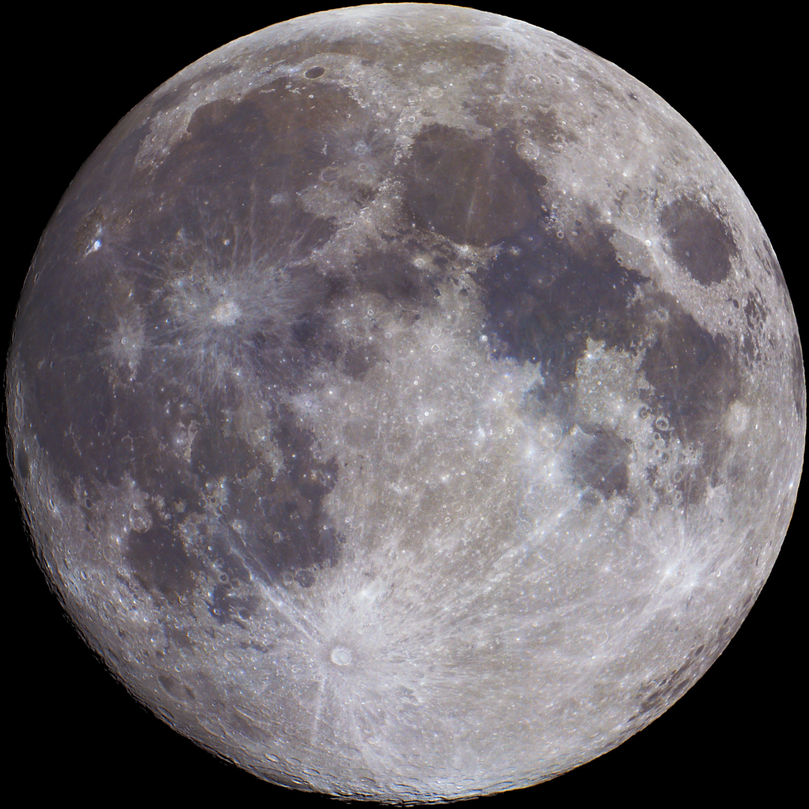
Contrary to an illusion of our Earth-bound perspective, the Moon does not orbit Earth's center, rather both Earth and Moon revolve around their common center of gravity, the barycenter of the Earth-Moon system. That moment of inertia, at any given time, is about one-third the distance from Earth's surface and its center GravitySimulator.com
Tidal effects are most notable in large bodies of water, but the solid Earth also deforms in response to the pull of the Moon’s gravity.  On both objects, a tidal bulge extends slightly above the mean radius of both Earth and Moon.  This bulge is not perfectly aligned with the geometric line that connects the centers of the two objects because both Earth and Moon are rotating, and it takes time for the solid bodies to deform plastically.  Thus, the tidal bulge of the rapidly spinning Earth slightly leads the Earth-Moon line, resulting in a constant increased tug at the Earth by the Moon, slightly slowing the rate of Earth’s rotation down.  At the same time, this leading tidal bulge attracts the Moon more, making it speed up in its orbital path slightly and thus, move outward, away from the Earth.  So over time, as the Earth spin rate slows, the Moon gradually recedes away from its grip; this rate of recession is about 4 cm per year.  The Moon is currently about 60 Earth radii away; it was once much closer, possibly as close as a few Earth radii.  It could not be closer than about 3 radii (the Roche limit) because at distances closer than the Roche limit, tidal forces would tear the Moon apart.  In a few hundred million years, the Moon will be too far away to permit a total solar eclipse to be seen from Earth.  A timely and good thing that we came along when we did!

Using information from a lunar seismic network deployed on the Moon during the Apollo missions, we know that “moonquakes” often correlate with the tidal flexing of the solid Moon induced by the Earth (which is much larger than the terrestrial bulge because Earth is much more massive).  In fact, although there is a slight suggestion that the Moon might induce the initiation of an earthquake, in most cases there is no obvious connection.  The Earth is an active, dynamic body and its great internal heat and complexity of configuration appear to be more important in determining when and where an earthquake occurs than by tidal effects caused by the Moon.  But if the proper tidal conditions and the alignment of stress and magnitude of effect coincided, there is no reason that either syzygy or Super Moon could not induce an earthquake.

Our Moon is much more than the familiar, comforting nightlight orbiting Earth.  Beyond touching us emotionally and affecting our planet physically, the Moon is also an orbiting treasure trove of, as yet unrealized (some imagined but mostly yet unimagined) scientific discoveries and technological breakthroughs.  But before we make it our goal to settle the Moon, we must make it our goal to sail beyond it.
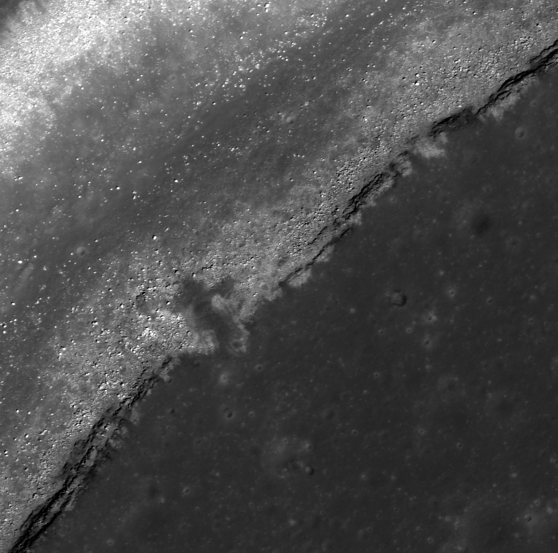
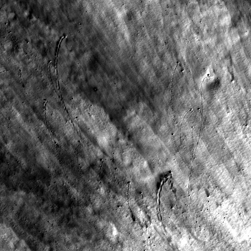
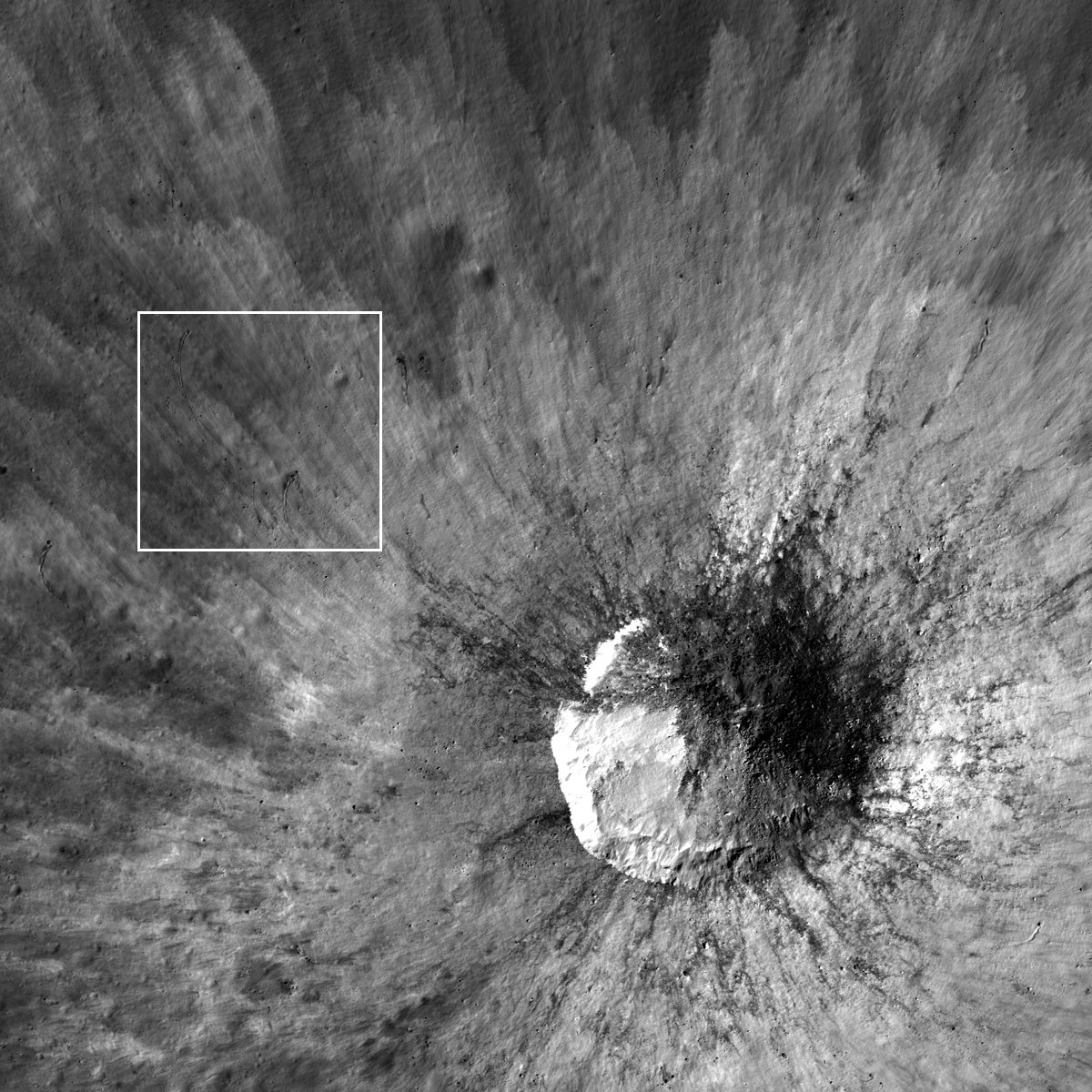
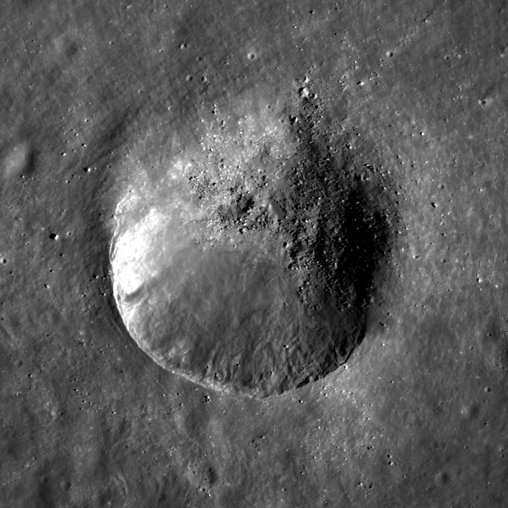
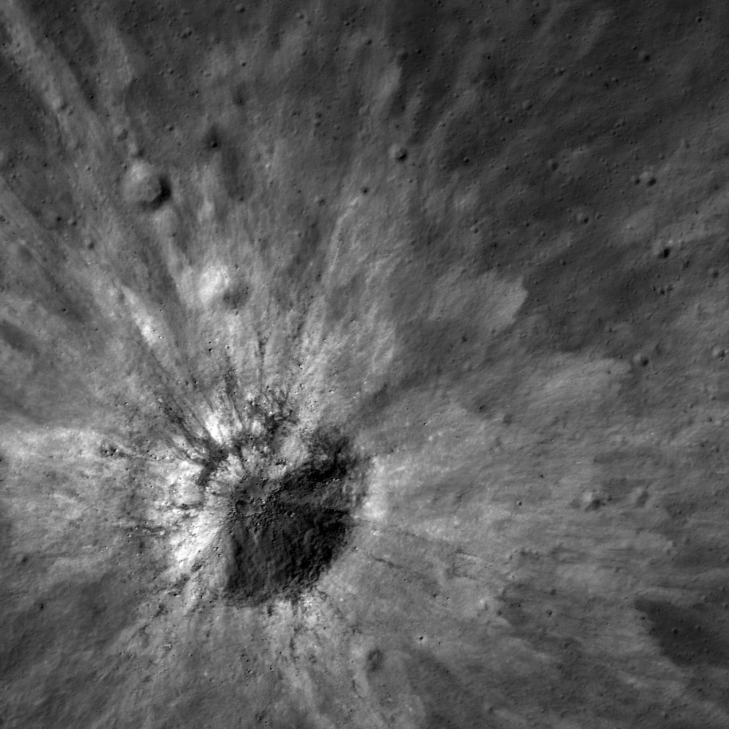
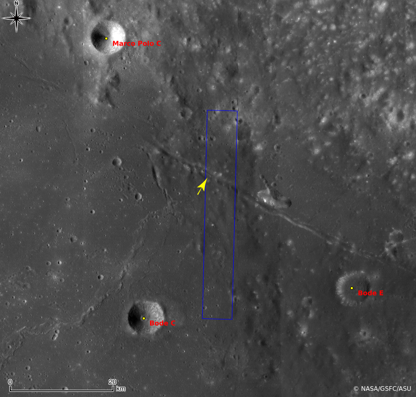
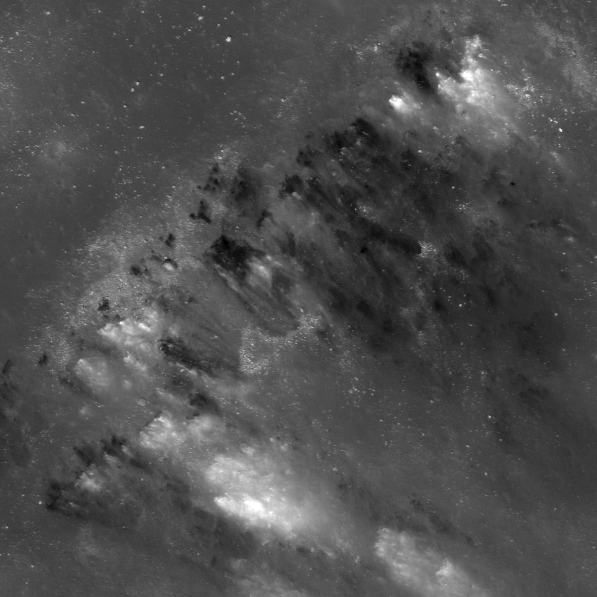
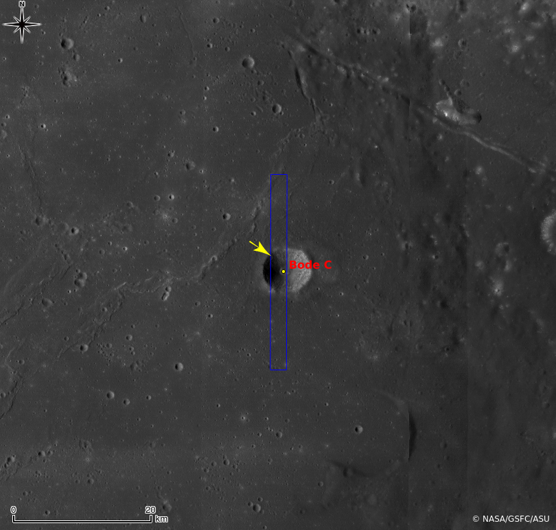
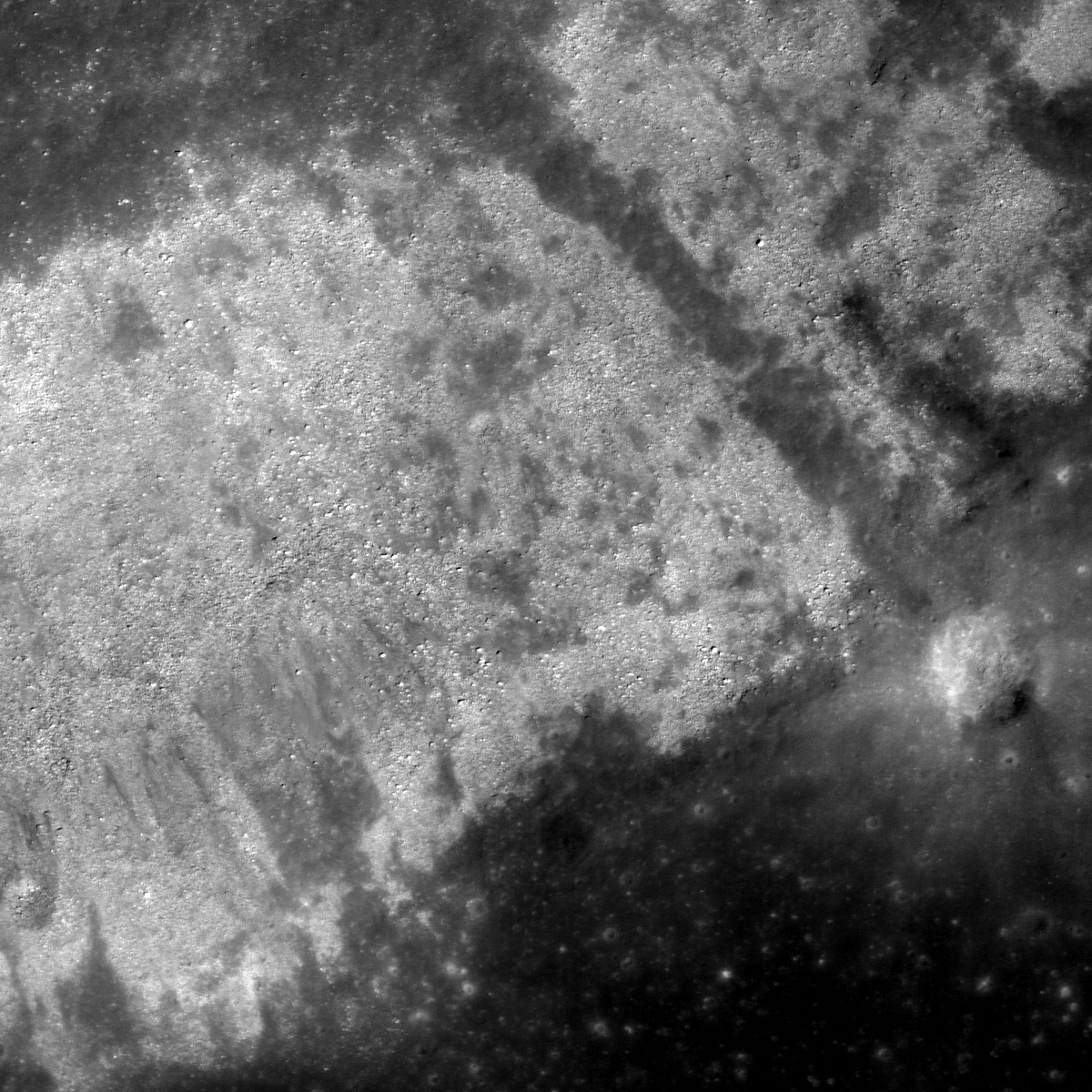
Originally published June 26, 2013 at his Smithsonian Air & Space blog The Once and Future Moon, Dr. Spudis is a senior staff scientist at the Lunar and Planetary Institute. The opinions expressed are those of the author but are better informed than average

Tuesday, June 25, 2013

Farside Boulders, Curve Northeastward

Curved boulder tracks outside the rim of a fresh crater on the farside highland terrain southeast of Mare Moscoviense. LROC Narr wo Angle Camera (NAC) observation M143594908L, spacecraft orbit 6295, November 10, 2010; field of view 320 meters across, 39.27° angle of incidence, resolution 58 cm per pixel from 55.36 km [NASA/GSFC/Arizona State University].
Sarah Braden
LROC News System

The boulders in the Featured Image all curve to the northeast, carving dark paths across the fresh rays from a small 525-meter crater on the lunar farside northeast of Van Gent U, 17.233°N, 157.367°E.

The boulders originated from the impact crater itself, being ejected during the impact event with a velocity radial to the crater rim.

As the boulders bounced and rolled along the surface they lost speed (kinetic energy) and slowed, creating gently curving paths until they came to a stop.

Wider field of view from LROC NAC M143594908L, context showing the location of the boulders with respect to their source crater in a field of view 1.9 km across [NASA/GSFC/Arizona State University].
The curved paths are likely caused by the preexisting slope of the topography, which is slightly downward sloping to the northeast (~10°). The linear striations of the fresh ejecta define the radial direction away from the crater and provide a beautiful contrast for the curved boulder paths.

Using the latest LROC QuickMap, a 2.09 by 2.09 km wedge of terrain is shown in 3D, and turned 90° counter-clockwise to show the wider slope where the crater of origin and boulder field are nested in the LROC WAC-derived digital terrain model. The local elevation, from south to north ranges approximately 240 to over 900 meters above global mean [NASA/GSFC/Arizona State University]/
Overall, the fresh material was ejected at higher velocities than the boulders so it is not influenced by the topography and remains on a trajectory radial to the crater.

Explore the entire fresh crater with the LROC NAC, HERE.

Related LROC Featured Images:
Hole in One!
Bounce, Roll, and Stop
Weaving Boulder Trails on the Moon
Rolling Rolling Rolling
Sampling Schrödinger
Central Peak/Mare Boundary

Thursday, June 20, 2013

An Oval Crater on Harvey's Wall

A bolide impacting into the sloping south wall of Harvey crater formed an oval rather than circular crater. A 1.32 km-wide field of view cropped from LROC Narrow Angle Camera (NAC) observation M191567120R, LRO orbit 13268, May 13, 2012; 56.78° angle of incidence, resolution 1.36 meters from 136.22 km [NASA/GSFC/Arizona State University].
Lillian Ostrach
LROC News System

Non-circular (oval or elliptical) impact craters can form when the impacting bolide trajectory to the surface is less than 15° from horizontal or when the bolide impacts a sloped region on the (or some combination of both factors). 

This young crater (18.855°N, 213.180°E) formed on the sloping southern wall of Harvey crater, which is very degraded, and may be an example in which target surface slope controlled final crater shape (as opposed to impact angle). The crater is oval-shaped, measuring ~735 m across and ~780 m in the north-south direction.

A closer look, under a higher sun, allows a detailed view of the bright ejecta of the crater of interest. Full 3 km-width field of view from LROC NAC M138504456L, orbit 5545, September 7, 2010; 29.65° angle of incidence, resolution 66 cm from 63.83 km [NASA/GSFC/Arizona State University].
A closer look, under a higher sun, allows a detailed view of the bright ejecta of the crater of interest. (View the very large, full-sized mosaic HERE.) Full 3 km-width field of view from LROC NAC M138506456L, orbit 5545, September 7, 2010; 29.65° angle of incidence, resolution 66 cm from 63.83 km [NASA/GSFC/Arizona State University].
The southern half of the crater has a well-defined, sharp rim with some concentric fractures (particularly visible on the southwestern rim area) while the northern rim is ill-defined.

LROC Wide Angle Camera (WAC) monochrome mosaic of Harvey crater (19.35°N, 213.49°E, ~60 km diameter). The fresh, oblique impact shown in the LROC Featured Image is on the crater wall, "like flour dropped on the floor," is below left center [NASA/GSFC/Arizona State University].
The poorly-developed northern rim indicates that the impact trajectory probably traveled from the south/southwest toward the north/northeast. In a lower incidence angle image (Sun approaches "noon" position overhead), the albedo variations emphasize the high-reflectance ejecta blanket (observed in the WAC mosaic below) and observations of the ejecta blanket, including the zone of avoidance, help confirm the bolide trajectory.

Harvey, in strategraphic context, itself nested on the northeastern rim of Mach. An arch rim of of an older crater can be seen to the north. The region is further effected by secondary craters from the Mare Orientale impact and elsewhere. LROC WAC-derived digital terrain model [NASA/GSFC/Arizona State University].
LROC NAC images reveal the presence of unexpected ponds of impact melt in small lunar craters. Taking a look at the northern portion of this small crater, there is a smooth deposit with slightly lower reflectance than the surrounding materials. This smooth material is probably a small pond of impact melt, generated during impact. Impact melt is likely distributed elsewhere within the crater as thin veneers, perhaps on the southern wall where there are lower-reflectance smooth streaks, and probably mixed in with the fragmented debris that were not ejected from the crater.

Explore this oval crater for yourself in the full LROC NAC image, HERE.

Related Posts
Tres Amicis
Clamshell
A Tiny, Glancing Blow

Wednesday, June 19, 2013

Complicated Crater

Impact melt, boulders, and mass wasting - oh my! Close-up on the interior of a "complicated," relatively fresh small crater on the floor of Mare Australe. LROC Narrow Angle Camera (NAC) observation M190007628LR, field of view 1 km, resolution 67 cm per pixel from 64.11 km [NASA/GSFC/Arizona State University].
Lillian Ostrach
LROC News System

Relatively fresh, undegraded craters are visually stunning. Today's Featured Image of the interior of a 1.7 km diameter crater (38.728°S, 88.697°E) exhibits just how geologically complicated craters can be! The crater rim is well-formed and relatively distinct, with ejected blocks nearby (some blocks might even fall inside the crater).

Portions of the upper crater walls have jagged, fractured material that may serve as the source for some of the mass-wasting observed lower on the crater walls. There is an approximately 350 meter diameter impact melt deposit on the crater floor. This smooth deposit exhibits polygonal cracks, possibly due to contraction as the melt cooled and hardened. Surrounding the impact melt pond are jumbled piles of blocks, some of which show evidence of impact melt veneer while other boulders landed after the impact melt pond cooled (but "how much later?" is a question we cannot answer easily).

M154649439LR
Slightly closer viewing opportunity. LROC NAC mosaic M154649439LR, orbit 7964, 41.98° angle of incidence, 52 cm per pixel resolution, from 49.26 km. View the very large full resolution crop HERE [NASA/GSFC/Arizona State University].

The wide range and contrast of the small crater's fan of ejecta, against the ancient floor of Mare Australe, may be easier to see in this medium resolution crop from the Global Mosaic stitched together from observations swept up by China's Chang'E-2 orbiter. The coloring reflects data collected by the Clementine orbiter in 1994.
LROC WAC monochrome mosaic of the fresh crater north, north of Gum (arrow) [NASA/GSFC/Arizona State University].
Although there are no deep gullies in the upper crater walls, the inter-weaved channels running down the crater walls suggest a complex relationship between impact melt and dry debris flows. The finger-like flow morphology, especially close to the floor melt pond, is similar to impact melt flows elsewhere. However, observations of dry debris flows in other lunar craters are sometimes difficult to distinguish from impact melt. Careful study of stratigraphic relationships is required in cases such as this one to distinguish which material may be melt or dry debris.

Observe the crater wall complexities for yourself in the full LROC NAC image, HERE.

Related Posts:
Farside impact!
Crater in 3D!
Symmetric Ejecta

The Moon's antipodal magnetism mystery

A new study of areas on the Moon opposite (at the antipodes) of the Moon's youngest basins goes beyond long-studied crustal magnetic anomalies and the albedo "swirls" at those opposite coordinates to demonstrate "highly modified terrain" at these opposing points. Animation from preliminary lunar crust thickness maps derived from GRAIL (2012) data by the Science Visualization Studio. [NASA/GSFC].
Paul D. Spudis
The Once and Future Moon
Smithsonian Air & Space


Although the Moon has no global magnetic field like the Earth, small areas on its surface are magnetized.  These fields are not systematically distributed and in general are very weak.  In trying to explain their mysterious presence and origin, several ideas have been advanced.

Rocks typically acquire magnetism (called remnant magnetism) by cooling in the presence of a magnetic field.  At temperatures greater than about 570° C (the so-called Curie point), a rock cannot retain a magnetic signature.  But if it cools below the Curie point, it assumes an induced magnetic field oriented in the same direction as the field in which it cooled.  Unfortunately, on the Moon most rocks have been dislodged from their original orientations by impact processes, so we do not know whether a given rock cooled in the presence of a global (presumably uniform strength and direction) or local (randomized) magnetic field.

We knew the Moon had no global magnetic field before the Apollo crews landed, so it was a bit surprising to learn that some of the returned lunar rocks are strongly magnetized.  Because these rocks are all very old (usually much older than 3 billion years), it was thought that they recorded an ancient epoch when the Moon might have had a global magnetic field, now vanished for some reason.

This finding from the lunar samples was complemented by measurements from orbit that show small areas (10s to 100s of kilometers across) of the surface to be magnetized.  These areas occur all over the Moon and are not associated exclusively with either the dark volcanic maria or the bright highlands crust.  However, they do tend to have two peculiar properties.  First, we find strange “grooved” terrain associated with some of the strongest magnetic anomalies.  This terrain is unlike any other lunar landform – it consists of ridges and valleys that cover the walls and sides of craters and mountains.  Second, these magnetic anomalies tend to occur at the antipodes of (180° away on the opposite side of the globe from) the largest and youngest lunar multi-ring impact basins.  These are curious properties indeed.  What might it mean?

For years, many have pondered and worked on this dilemma.  One idea was developed that perhaps these magnetic anomalies are formed during basin impact.  It was proposed that seismic shaking from these enormous impacts created the grooved terrain and induced fractures in the crust at the antipode, into which hot volcanic magma was injected.  After cooling these dikes assumed remnant magnetism from a global dipole field.  Yet another idea contends that the concentration of magnetized material is a result of antipodal convergence of basin ejecta, which arrived hot from basin formation, collected at the antipode and cooled through the Curie point there.  This last model has the advantage that it might also explain the presence of the grooved terrain, which might have formed by the arrival of basin ejecta on the surface from impacts coming from all directions simultaneously.

Though islands of crustal magnetism are strongly associated with points diametrically opposite from basin forming impacts, these magnetic anomalies are also often offset from those antipodal points. Above, the ring of the Moon's youngest basin Schrödinger, in the far lunar south, is mirrored on the area on the direct opposite side of the Moon in the far lunar north. The absolute antipode is in the vicinity of Anaximenes H. The crustal magnetism mapped using Lunar Prospector data seems at its highest near Catena Sylvester. Terrain cited as greatly disrupted seismically is further still from the Schrödinger antipode, at craters Froelich and Lovelace, just beyond this field of view, at upper right [NASA/GSFC/ASU].
My colleague Lon Hood from the University of Arizona has been studying magnetic anomalies for many years and is an advocate of the last model described above.  Hood was studying some previously ignored, smaller magnetic anomalies found around the Moon that had no explanation. He asked me about the geological setting of one particular magnetic anomaly on the Moon that had yet to be described in detail.  This one occurs in highlands near the north pole of the Moon and had not been previously studied in detail.

I have been something of a skeptic for many years about the basin/antipode relation for magnetic anomalies.  Part of the reason for my position is the problem of Reiner Gamma, which is a bright patch on the lunar surface that has one of the highest magnetic field strengths on the Moon.  The problem is that Reiner Gamma is nowhere near the antipode of any basin and shows no evidence for any grooved terrain.  So I thought that this was the exception that disproves the rule.
“Will your grace command me any service to the world's end?  I will go on the slightest errand now, to the Antipodes that you can devise to send me on…”
- Much Ado About Nothing, (Act II, scene 2)

Nonetheless, I was intrigued by Hood’s finding and decided to examine the area.  To my astonishment, I found wall textures very similar to the famous grooved terrain in the walls of the craters Lovelace and Froelich (not exactly coincident with the anomaly, but very close).  I can see no obvious reason for such terrain development; it appears to be highly restricted in its distribution and is not a fresh feature.  Judging from its degraded appearance, it is rather old.

So, is there a basin antipodal to Lovelace and Froelich?  Indeed there is – the fabulous Schrödinger basin, one of the smaller lunar basins at 325 km diameter, located near the south pole of the Moon.  Before our study, I probably would have thought that Schrödinger was too small to create any global-scale effects, but we don’t fully understand the effects of impact with increasing size and there is no good alternative explanation for the wall textures of these two craters.  The presence of a significant magnetic anomaly nearby is unquestionable.

Froelich (l) and Lovelace (r), adjacent to Catena Sylvester (above map) and the region antipodal to Schrödinger basin - showing grooved terrain in walls (green arrows).
From Hood, et al (2013). Along with its spectacular lunar swirls and complex crustal magnetism, grooved terrain along the walls surrounding Mare Ingenii is also a easily identified characteristic of the region adjacent to the antipodes of Mare Imbrium. Less well-known, perhaps, is the region antipodal to Mare Serenitatis, along the north rim of the more ancient South Pole-Aitken basin [NASA/GSFC/ASU].
So have I changed my mind on the origin of lunar magnetic anomalies?  Possibly.  One of the most convincing ways to get a scientist to change his mind is to bludgeon him with an irrefutable fact that contradicts his worldview.  I now realize the Reiner Gamma problem does not “disprove” the basin antipode model – it merely indicates that it may be incomplete.  That distinction is subtle but significant.  In science, we always look for “rules,” generalities that help us organize observations and suggest possible explanations.  However, these rules sometimes have exceptions and we must carefully distinguish which actually have the force of a rule versus those that merely indicate some general tendencies.

To me, this discovery was surprising.  The new finding still does not fully address exactly how these magnetic anomalies are formed at the antipodes, but the concept that magnetic anomalies and basin-forming impacts are intimately associated has been strengthened and extended.  We will continue to work on this vexing problem.

Originally published June 19, 2013 at his Smithsonian Air & Space blog The Once and Future Moon, Dr. Spudis is a senior staff scientist at the Lunar and Planetary Institute. The opinions expressed are those of the author but are better informed than average.

Related Posts:
Bubble, Bubble – Swirl and Trouble (July 19, 2012)
Boulder 668 at Descartes C (July 16, 2012)
LROC: The Swirls of Mare Ingenii (June 22, 2012)
Remnant magnetism hints at once-active lunar core (January 27, 2012)
Grand lunar swirls yielding to LRO Mini-RF (October 4, 2010)
Another look at Reiner Gamma (June 30, 2010)
LOLA: Goddard (June 26, 2010)
Depths of Mare Ingenii (June 16, 2010)
LROC: Ingenii Swirls at Constellation Region of Interest (May 26, 2010)
Local topography and Reiner Gamma (May 22, 2010)
Lunar swirl phenomena from LRO (May 17, 2010)
The still-mysterious Descartes formation (May 11, 2010)
Dust transport and its importance in the origin of lunar swirls (February 21, 2010)
The Heart of Reiner Gamma (November 17, 2009)
Moon’s mini-magnetospheres are old news (November 16, 2009)
MIT claim of solving ‘lunar mystery’ unfounded (January 15, 2009)

Tuesday, June 18, 2013

"Ka Pow!" on Joliot's central peaks

High-reflectance ejecta and low-reflectance impact melt streamers surround this fresh impact crater on the slopes of the central peak formation of Joliot crater. LROC Narrow Angle Camera (NAC) mosaic M189994606R, LRO orbit 13048, April 25, 2012; field of view 2.25 km, 43.12° angle of incidence at 1.11 meters per pixel resolution, from 147.53 km [NASA/GSFC/Arizona State University].
Lillian Ostrach
LROC News System

High-reflectance ejecta blankets the terrain surrounding a 650 meter diameter crater (26.525°N, 93.518°E).

From samples collected during the Apollo missions we know that high-reflectance ejecta represents recently exposed material that has not yet been affected by space weathering processes (maturity rays) or material exposed that is a different composition than the surrounding area (compositional rays).

The impact crater in the opening image formed near the base of the central peak of Joliot crater (172.79 km in diameter, 25.79°N, 93.39°E), the floor of which was partially flooded with volcanic material. What type of ejecta rays are observed in today's Featured Image - compositional or maturity?

LROC WAC monochrome mosaic of the central interior of Joliot crater, with a fresh impact (arrow) at the base of the central peak complex [NASA/GSFC/Arizona State University].
The crater formed on the base of the central peak which is likely highlands material. The rays extend outward more than two crater diameters onto the mare material. Thus we have an example that is both a maturity ray and compositional ray. Over time as the ejecta matures, the portion on the highlands material will be indistinguishable, while the portion on the mare will still be visible. The much larger crater Tycho (93 km diameter) shows the same combination maturity-compositional rays.

Explore the full LROC NAC image for yourself; HERE. Do you see evidence for impact melt and if so, what do you see (ponds, streamers, flows)?

Related Posts:
Polka-dot Ejecta
Ejecta Starburst
Symmetric Ejecta
Ejecta Sweeps The Surface
Minty Fresh

Thursday, June 13, 2013

Revealed Surface, eastern Mare Insularum

Southern slope of unnamed fracture along the eastern mare/highland boundary of Mare Insularum. LROC Narrow Angle Camera (NAC) frame M1114199297R, LRO orbit 16439, January 30, 2013; 1147.2 meter field of view centered on 13.135°N, 355.638°E, 42.94° angle of incidence, resolution 0.96 meters per pixel from 114.18 km. (Downslope toward upper-right, north at top) [NASA/GSFC/Arizona State University].
Hiroyuki Sato
LROC News System

Today's Featured Image highlights a portion of an unnamed linear fissure located along the eastern edge of Mare Insularum, near the mare/highland boundary.

The width of this fissure varies from about 1.5 to 2 km, its  length is about 90 km, and it extends in the northwest-southeast direction.

The upper-right portion of the opening image, showing a shallow groove extending from up to middle right of the image, corresponds to the bottom of the fissure. Thus most of the image reveals the southern wall of the fissure.

The LROC Featured Image field of view rendered approximately in elevation data from the LROC WAC DTM. Local slopes in the vicinity of the fracture of interest can be difficult to otherwise see. LROC QuickMap [NASA/GSFC/DLR/Arizona State University].
On this slope, there is a high reflectance area with sinuous boundaries. This unit is hard to interpret in terms of what is on top and what is below, stratigraphically. The sunlight is from left side, highlighting what appears as a slightly raised boundary between the two units (arrows). Elsewhere it looks as if the high reflectance material overlies the lower reflectance material. Which unit is younger? Try counting craters between the two, but be careful, if the units have different hardnesses, then the more coherent unit may preserve craters better. 

Unnamed fracture running northwest to southeast on the eastern side of Mare Insularum and surrounding vicinity in LROC WAC monochrome mosaic (100 meters per pixel), centered is 13.12°N, 355.66°E. The LROC NAC footprint (blue box) and location of the field of view in the Featured Image (yellow arrow) are marked [NASA/GSFC/Arizona State University].
Since this whole area is on a slope, slope failure may have revealed an underlying immature surface. Indeed multiple higher reflectance boulders are sitting at the downslope side of this high reflectance unit. But the upper complicated shapes are difficult to explain by this simple story. Or perhaps low reflectance materials could have slumped and covered portions of the high reflectance material? A high resolution NAC DTM would help scientist unravel this complicated morphology.

Explore this enigmatic patterned surface in full NAC frame yourself, HERE.

Related Posts:
Inside Hyginus Crater
Bright ridge near Mons Hansteen
Wrinkle Ridge vs. Impact Crater
Really Wrinkled
Boulders In The Sea Of Serenity
Ghost crater in Mare Imbrium
Zebra Stripes
Aitken Central Peak, Seen Obliquely
Constellation Region of Interest at Mare Tranquillitatis

Wednesday, June 12, 2013

Layer of Pyroclastics in Sinus Aestuum

Northeastern wall of Bode C crater. LROC NAC M139938121L, a 600 meter field of view centered on 12.276°N 355.165°E; LRO orbit 5756, 0.50 meters resolution from 46.26 km. Downslope toward bottom right, north at top [NASA/GSFC/Arizona State University].
Hiroyuki Sato
LROC News System

Today's Featured Image highlights the slope of the northeastern crater wall inside Bode C.

The Bode C crater is 7 km in diameter, and located at eastern edge of Mare Insularum.

Low reflectance material flowed down the middle of the wall, possibly indicating a subsurface layered structure of low reflectance materials along this elevation.

M139938121R-NSJ-0306-58bx-5800x8000
High sun (15.07° angle of incidence) over Bode C, in context of a full width mosaic of both the left and right frames of LROC NAC M139938121LR [NASA/GSFC/Arizona State University].
Dark streaks are found along an almost constant elevation throughout the whole crater. Thus the spatial extent of this layer is likely more than the crater diameter.

Bode C in relation to the Rima Bode pyroclastics of Sinus Aestuum, from the Chang'e-1 global medium resolution mosaic [CNSA/CLEP].
Rima Bode, one of many Dark Mantle Deposits (DMD), is located about 20 km east from this crater. DMDs are thought to be formed as fire fountaining eruptions spread ash around a vent. The size of Rima Bode is about 70 by 80 km, with a crescent shape extending northwest and southwest direction. If this DMD distributed ash to the west, Bode C could have excavated this layer of Rima Bode's pyroclastics, thus explaining the dark streaks on its crater wall. High resolution images of impact craters give scientists a lot of information about the crater itself, but also tell about the surrounding geologic structures and history. 

LROC WAC monochrome mosaic (100 m/pix), centered on 6.14°N, 177.60°E. The NAC footprint (blue box) and location of opening image field of view (yellow arrow) are indicated [NASA/GSFC/Arizona State University].
Explore the streaks of low reflectance materials inside Bode C in full NAC frame, HERE.

Related Posts:
Rima Bode: Constellation Region of Interest
Pyroclastic Trails
Hyginus Crater and Pyroclastics
Dark Wisps in Copernicus
Dark streaks in Diophantus crater
Low Reflectance Deposits on the Lassell Massif
DMD Excavations
Pyroclastic Excavation

CRaTER on LRO shows lighter materials may better mitigate cosmic ray health risks

As CRaTER, flying with LRO, closes out a fourth year in lunar orbit, long duration exposure to cosmic rays while traveling within and beyond Earth's magnetic field shows materials lighter than traditional aluminum and titanium alloyed hulls may reduce the probability of Radiation Exposure Induced Death (REID) [NASA/GSFC/UHN/SwRI].
University of New Hampshire - Durham –- Space scientists from the University of New Hampshire (UNH) and the Southwest Research Institute (SwRI) report that data gathered by NASA’s Lunar Reconnaissance Orbiter (LRO) show lighter materials like plastics provide effective shielding against the radiation hazards faced by astronauts during extended space travel. The finding could help reduce health risks to humans on future missions into deep space.

Aluminum has always been the primary material in spacecraft construction, but it provides relatively little protection against high-energy cosmic rays and can add so much mass to spacecraft that they become cost-prohibitive to launch.

The scientists have published their findings online in the American Geophysical Union journal Space Weather. Titled “Measurements of Galactic Cosmic Ray Shielding with the CRaTER Instrument,” the work is based on observations made by the Cosmic Ray Telescope for the Effects of Radiation (CRaTER) on board the LRO spacecraft. Lead author of the paper is Cary Zeitlin (zeitlin@boulder.swri.edu) of the SwRI Earth, Oceans, and Space Department at UNH. Co-author Nathan Schwadron of the UNH Institute for the Study of Earth, Oceans, and Space is the principal investigator for CRaTER.

“This is the first study using observations from space to confirm what has been thought for some time—that plastics and other lightweight materials are pound-for-pound more effective for shielding against cosmic radiation than aluminum," Zeitlin said. "Shielding can’t entirely solve the radiation exposure problem in deep space, but there are clear differences in effectiveness of different materials.”

The plastic-aluminum comparison was made in earlier ground-based tests using beams of heavy particles to simulate cosmic rays. “The shielding effectiveness of the plastic in space is very much in line with what we discovered from the beam experiments, so we’ve gained a lot of confidence in the conclusions we drew from that work,” says Zeitlin. “Anything with high hydrogen content, including water, would work well.”

The space-based results were a product of CRaTER’s ability to accurately gauge the radiation dose of cosmic rays after passing through a material known as “tissue-equivalent plastic,” which simulates human muscle tissue. 

Prior to CRaTER and recent measurements by the Radiation Assessment Detector (RAD) on the Mars rover Curiosity, the effects of thick shielding on cosmic rays had only been simulated in computer models and in particle accelerators, with little observational data from deep space.

The CRaTER observations have validated the models and the ground-based measurements, meaning that lightweight shielding materials could safely be used for long missions, provided their structural properties can be made adequate to withstand the rigors of spaceflight.

Since LRO’s launch in June 2009, the CRaTER instrument has been measuring energetic charged particles— often very heavy and spectacularly energetic particles traveling at nearly the speed of light and cause detrimental health effects—from galactic cosmic rays and solar particle events (SPE's). 

Fortunately, Earth’s thick atmosphere and strong magnetic field provide adequate shielding against these dangerous high-energy particles.

To view the Space Weather article (behind academic pay wall), visit http://onlinelibrary.wiley.com/doi/10.1002/swe.20043/abstract

For more on the CRaTER instrument, visit http://crater.sr.unh.edu/ and for the LRO mission visit http://lunar.gsfc.nasa.gov/mission.html.

Related Posts:

Tuesday, June 11, 2013

Slope Resurfacing

Southeastern wall of Jansen U crater. LROC Narrow Angle Camera (NAC) observation M188028576R, spacecraft orbit 12773 April 2, 2012; 18.45° angle of incidence, resolution 0.98 meters from 120.28 km, 1182.3 meter-wide field of view centered on 11.926°N, 32.306°E (Downslope toward upper left, north at top) [NASA/GSFC/Arizona State University].
Hiroyuki Sato
LROC News Service

Today's Featured Image highlights the wall of Jansen U crater, located at the northeast section of Mare Tranquillitatis. Jansen U is a 3.28 km diameter crater with a teardrop shaped cavity, and likely originated from a low angled oblique impact (see next NAC context image).

The high reflectance area includes many boulders is the crater wall. The low reflectance area in the lower right of the image, which includes a smaller crater (~130 m in diameter), is the rim and shallowly sloping ejecta blanket. The upper left corner of the image, which is covered by low reflectance materials (but not as low as the background surface), corresponds to the crater floor.

Jansen U crater in NAC context image, center on 11.955°N, 32.304°E, field of view about 4 km. The Featured Image corresponds to the field of view outlined by the white box [NASA/GSFC/Arizona State University].
Jansen U crater has an eye-catching appearance due its ovoid shape and brilliant contrast between the low reflectance floor higher reflectance crater walls. Since no indication of impact melt is seen on the crater floor (e.g. fractures or viscous flow features), the floor is likely covered by post impact in-filling materials. Little by little space weathering produces the mature regolith everywhere on the surface, while the slope failure slumps mature material away continuously. These mass wasting and weathering processes often result in striking albedo patterns. 

Jansen U and surrounding Mare Tranquillitatis in LROC WAC monochrome mosaic (100 m/pix), centered on  6.15°N, 16.17°E. The NAC footprint (blue box) and the location of the field of view in the LROC Featured Image (yellow arrow) are indicated [NASA/GSFC/Arizona State University].
Explore Jansen U crater, contrasting reflectance patterns of the wall and the floor in the full NAC frame, HERE.

Related Posts:
Downhill Creep or Flow?
Leathery vs smooth surface
Slope failure near Aratus crater
Crater Covered With Boulders!
Bright ridge near Mons Hansteen
Multiple Flow Lobes

Lunar Orbiter images last seen 47 years ago

Lunar Orbiter 2 frame 159 (H2), an approximately 4.5 by 6 kilometers stretch of lunar mare 250 km southwest of Copernicus. One of three high-resolution photographs swept up, developed, scanned and radioed back to Earth in 1966. The fully-restored, previously incomplete session has been restored by the Lunar Orbiter Image Restoration Project (LOIRP).
Keith Cowing
LOIRP

After being forgotten for nearly 47 years, three high resolution images taken by the Lunar Orbiter II spacecraft have been rediscovered by the Lunar Orbiter Image Recovery Project (LOIRP).

It is unlikely that anyone has seen these images since they were sent back to Earth. Indeed, it is unlikely that very many people saw them at that time either.

The three high resolution images were taken along with a medium resolution image on 23 November 1996 at 17:05:39 GMT. The center point of the images was 26.94 West Longitude, 3.196 degrees North Latitude. The images were taken at an altitude of 43.6 km and the image resolution is 0.93 meters.

Thumbnail of the medium resolution image, from the Lunar and Planetary Institute catalog. The area captured at high resolution in November 1966 is outlined at center. The area seen in "H2" above is outlined in yellow. This region is characterized by ejecta and secondary craters, primarily radiant from the Copernicus impact from 250 km northeast.
We recently came across these three images (#2159) and noticed that they do not appear online at the LPI Lunar Orbiter database. Only the medium resolution image gets mentioned at LPI.

These three images were retrieved from original Lunar Orbiter program analog data tapes yet they appear nowhere in NASA's publications. They do appear on microfilm archives at LOIRP and are mentioned in a simple data log online at LPI. LOIRP has a more extensive computer printout of this data that shows more detail about the images - but not the images themselves.

Among the highest resolution Wide Angle Camera images of the region, among LROC images thus far released to the Planetary Data System (PDS), the area of interest is smaller than a postage stamp, above the right (east) central edge of this 32.4 km-wide field of view from LROC Wide Angle Camera (WAC) observation M166025782C (604 nm), LRO orbit 9601, July 23, 2011; 62.86° angle of incidence, resolution 55.85 meters per pixel from 40.64 km [NASA/GSFC/Arizona State University].
Unless someone happened to be looking through this microfilm collection (LOIRP has the only extant copy) then it is pretty safe to assume that no one has actually seen these images since a technician saw them on a TV monitor in 1966.

Read the full article, catch up on the Lunar Orbiter Image Restoration Project,
and discover how you can help
, HERE.