Showing posts with label Lunar topography. Show all posts

Wednesday, April 10, 2013

John Moore's "Watered Moon"


John Moore has a new video quite different than what we've posted of his work previously. About the video above he recommends:
"Several theories abound as to the Moon's formation. One in particular is 'The Giant Impact Theory', which suggests a Mars-sized object struck our proto-Earth, and ejected vast amounts of material that later accreted to form the Moon. The two worlds developed quite differently over time -- one sustaining [life as we know it], the other a barren landscape completely indifferent to our natural needs. Central to formation of life on Earth was water, which fueled the diversity of life at every level. For the Moon, however, it wasn't to be so. But what if the conditions were just right, and water could sustain on the lunar surface, what then would have been the outcome? Let's see..."
Without unnecessary delay, we'll include the following additional work by John, though it deserves its own post with explanatory illustrations. It deserves its own Poster. As it is, we include links to earlier related posts since these two extremities of lunar elevation, first identified by Japan's Kaguya investigators and refined by American teams using data from LRO, have been of particular interest here.


Related Posts:
Oblique views of the Moon's highest and lowest places (October 3, 2012)
View from Vavilov (January 31, 2012)
DLR: Flying over the three-dimensional Moon (December 1, 2011)
LROC's new Global Lunar Topography (November 16, 2011)
LOLA's deep Antoniadi (April 16, 2011)
LRO's unprecedented topography of the Moon (December 17, 2010)
Highest point on the Moon (October 26, 2010)
The deepest spot on the Moon nearly wasn't (September 17, 2010)
Lunar superlatives from LROC WAC (September 6, 2010)
The Moon's lowest of the  low (November 24, 2009)
Accurate topographic map of the Moon (June 13, 2009)
Spectacular refinements to Kaguya laser altimetry (May 28, 2009)
Best lunar topography derived from Kaguya (February 12, 2009)

Tuesday, February 12, 2013

A Lunar Dichotomy

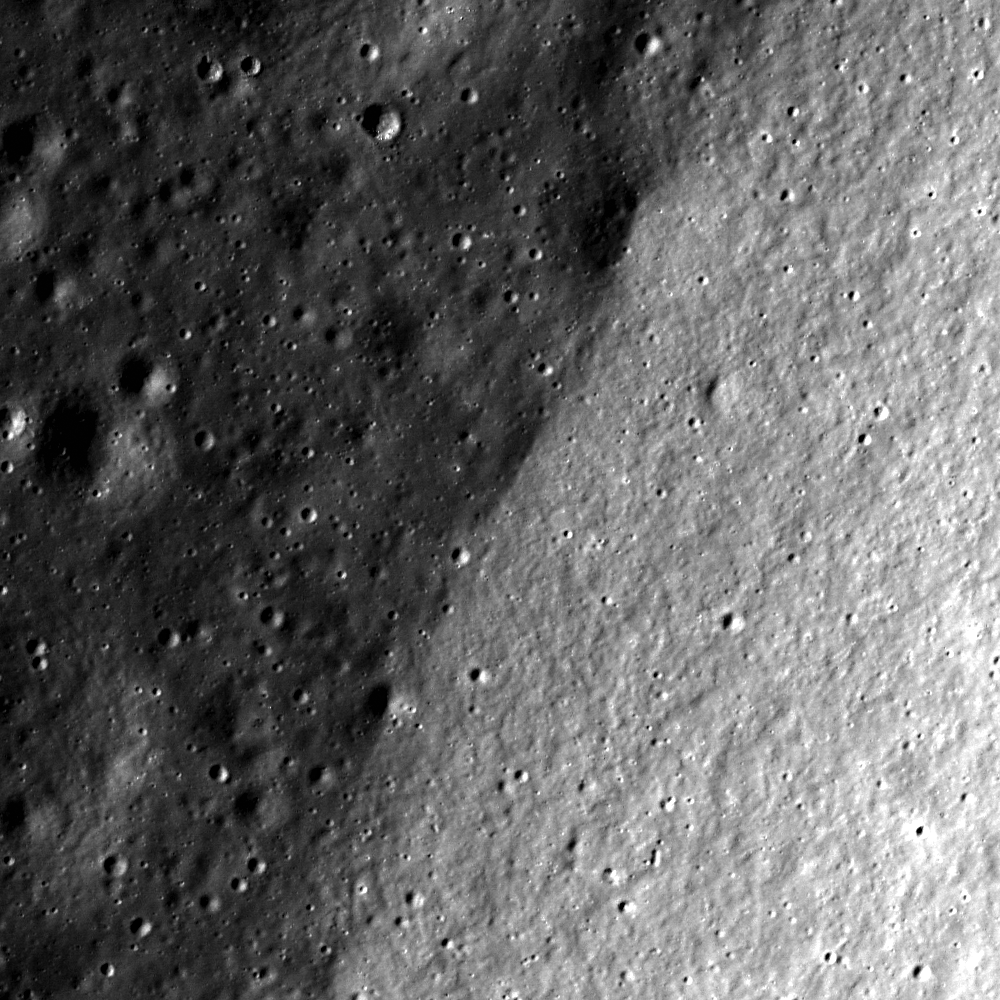
This LROC Narrow Angle Camera (NAC) frame exposes two seemingly different lithologies; one dark with several craters, and one light with few. What are we observing? LROC NAC observation M1113062041RE, spacecraft orbit 16278, January 17, 2013; 70 cm resolution of a field of view 700 meters across [NASA/GSFC/Arizona State University].
Drew Enns
LROC News System

Today's Featured Image shows a very interesting dichotomy on the Moon. One half of the image displays a dark cratered surface, while the other half is lighter in tone with less craters and a different texture. What could cause the difference in brightness, cratering, and texture? What sort of geologic contact are we observing?

Perhaps the bright material is younger, and as a result has fewer craters. Young lunar craters and their ejecta have a higher reflectance than older ones, and their ejecta blankets are only lightly cratered. The darker material could be older lunar terrain that the ejecta has overlain, and we are looking at the contact between these two surface types.

We could also be observing the interior of a crater. The texture of the brighter material is consistent with textures we see on sloped surfaces such as a crater wall. The difference in crater density can be explained as a result of the sloped wall of the crater. The darker half might then be the impact melt at the bottom of the crater floor.

Another hypothesis might be that we are observing the geologic contact between mare basalts and the lunar highlands. The mare are darker than the highlands but should have fewer craters. But that is not what we observe, unless the lighter material is on a slope (such as in our crater interior hypothesis). Which one of these hypotheses is correct? Let's look at a contextual view from the LROC WAC for help.

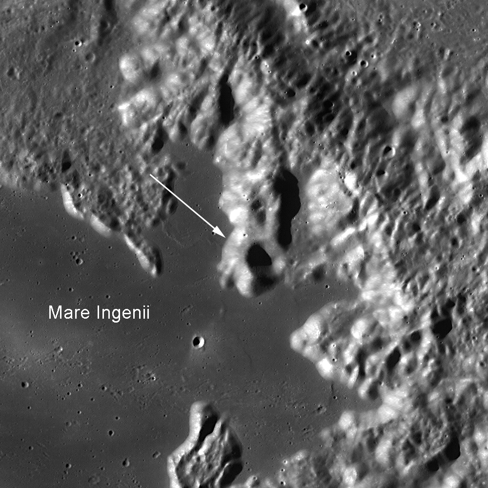
Context LROC Wide Angle Camera (WAC) 100 km-wide field of view designating the location shown at high resolution in the LROC Featured Image, released February 12, 2013. Northeast Mare Ingenii, just beyond the nearly buried rim of Thompson crater on the lunar far side. The contact coordinates are 31.069°S, 168.657°E. This Image width is 100 km [NASA/GSFC/Arizona State University].
The WAC mosaic provides the means to test our hypotheses instantly! The Featured Image is observing the geologic contact between mare basalts in Mare Ingenii and the surrounding highland material. This contact is important for the Moon since the mare and highlands are the two major rock lithologies present on the lunar surface. In fact, we can see this contact while standing outside at night and looking up at the Moon with the naked eye! While Mare Ingenii is on the farside of the Moon, the nearside maria are easy to distinguish against the lighter backdrop of the lunar highlands.

Apollo 15, beginning its 14th orbit, 1971, reemerging into day high to the northwest, delivered this beautiful oblique context photograph of the area of interest, Thompson crater and the surrounding quadrant of northeast Mare Ingenii (the contact is near center in this full resolution inset from AS15-87-11724) in the stark relief of the lengthening shadows of late afternoon [NASA/JSC].
The full frame of the Apollo 15 frame of Mare Ingenii taken from a point nearly antipodal to the expedition's landing site at Hadley Rille. Catch the high-resolution reproduction at the Apollo Lunar Surface Journal HERE [NASA/JSC/ALSJ].
Explore more of the Mare Ingenii and the nearby highlands massifs in the full LROC NAC, HERE

Related Posts:
Approach to Taurus Littrow Valley
Follow the highlands-mare boundary in Tsiolkovskiy!
Mare Moscoviense Constellation Site

Nearly forty years later, Japan's unmanned lunar orbiter SELENE-1 (Kaguya) captured Mare Ingenii in breathtaking HDTV, including the ancient impact basin's distinctive albedo swirl fields (left) precipitated over anomalous local magnetic fields. It's what most planetary scientists think of when the Sea of Ingenuity is under discussion. The area highlighted in the LROC Featured Image is near the Ingenii basin's northwestern extremes but also just beyond the huge Thompson ghost crater (center. See inset below) [JAXA/NHK/SELENE].
Inset from the oblique HDTV still of Mare Ingenii, the location near the field of view captured in the LROC Featured Image designated with an arrow. The swirls of Mare Ingenii draw the eye in the full-size 16:9 still, though far beyond the Ingenii basin rim, hugging the horizon, is most of the oblong, equally intriguing interior of the Van de Graaff basin. All of these scenes, and beyond, are a part of the widespread South Pole-Aitken basin [JAXA/NHK/SELENE].

Tuesday, October 23, 2012

Beautiful Young Crater in Icarus

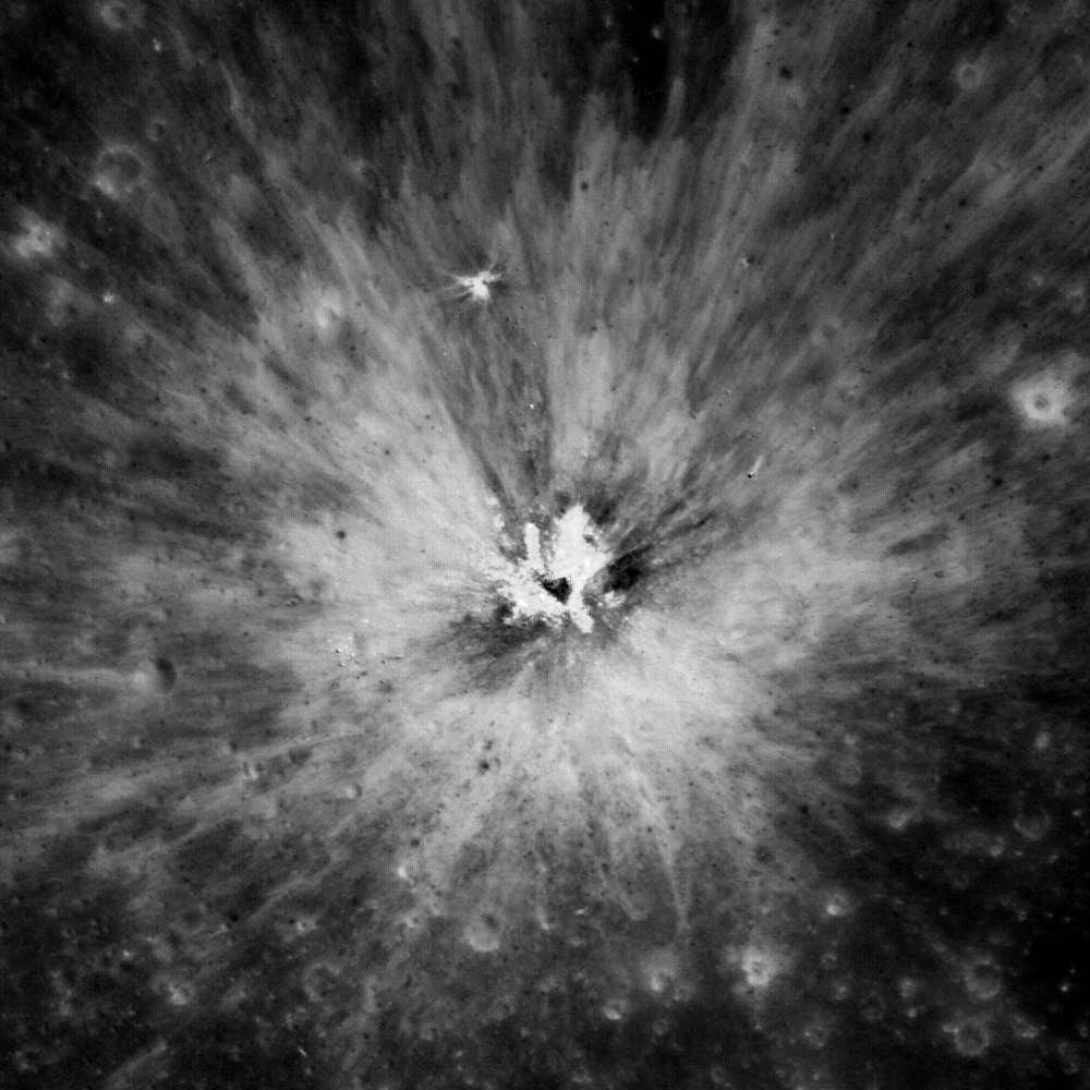
A beautiful, young crater inside of the complex crater Icarus. Field of view 550 meters from LROC Narrow Angle Camera (NAC) observation M156367058L, LRO orbit 8177, April 2, 2011; 0.6 meters resolution over an angle of incidence 10.53° from 58.61 kilometers [NASA/GSFC/Arizona State University].
Sarah Braden
LROC News System

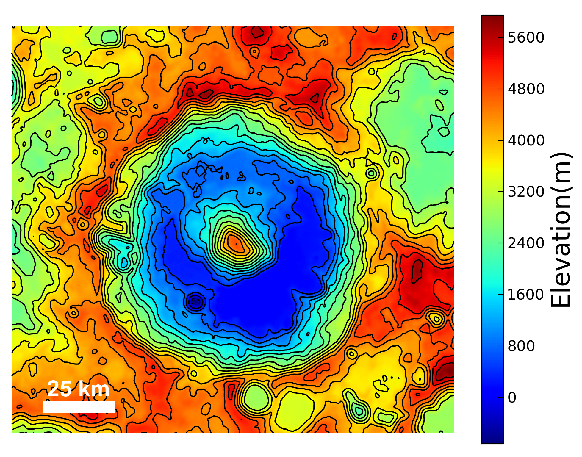
Icarus is a large, complex crater (diameter 93.7 km) with a central peak, located at 5.584°S, 186.998°E. Icarus is named after the mythical Greek flyer. The Featured Image shows a young, fresh crater (located at 5.929°S, 187.696°E) superposed on the older terraces of Icarus. The ejecta of the impact is higher in reflectance compared to the surroundings since the newly excavated material has been exposed to space weathering for a relatively short time. Over time space weathering causes the reflectance of fresh regolith to decrease. The ejecta of the crater in the Featured Image will fade over hundreds of millions of years, until it can no longer be distinguished from the rest of Icarus crater.

While the rim and terraces of Icarus are heavily degraded by subsequent impacts, the crater's central peak is still quite tall. The central peak rises about 4475 meters above the crater floor! Compared to other craters of similar diameter, this is quite a tall central peak! Consider many of the other complex craters with central peaks featured in the LROC images: Moretus, Hayn, Aristarchus, Theophilus, Bullialdus, Langrenus, Copernicus, and Tsiolkovskiy. For example, Tycho (~82 km in diameter) crater's central peak is 2 km above the crater floor.

Topography of Icarus crater. The northeast edge of the rim is partially destroyed [NASA/GFSC/Arizona State University].
All of these complex craters have a few common characteristics. First, the impact has to be large enough to cause a complex crater. Relatively smaller impacts create simple craters, which are bowl-shaped and have no central peak or terraces. After the excavation phase of the impact, the transient cavity collapses. This collapse is driven by gravity, which causes the uplift of the central peak as well as the collapse of the rim inward, which forms terraces along the interior wall. Some times an impact is so large that it creates a ring of peaks instead of just one central peak.

LROC Wide Angle Camera (WAC) context image of Icarus, the white asterisk marks the location of the fresh crater in the Featured Image [NASA/GSFC/Arizona State University].
Explore more of the interior of Icarus with this LROC NAC, HERE.

Related Images:
Lunar Topography - As Never Seen Before!
Copernicus Central Peak From The West
View From The Other Side

Wednesday, May 2, 2012

LROC NAC DTM: Copernican crater in 3D

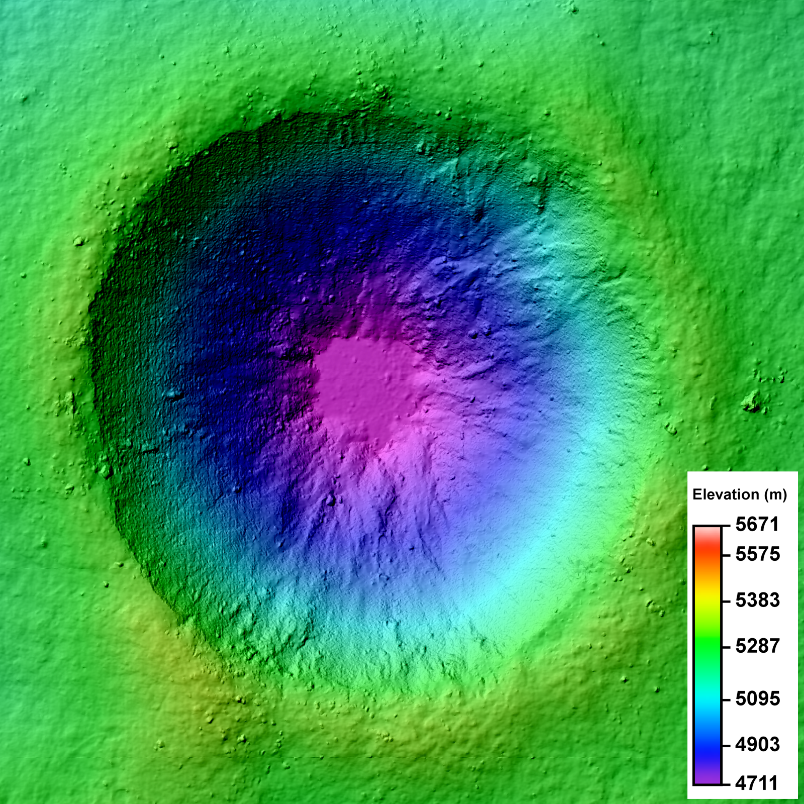
LROC Narrow Angle Camera (NAC) Digital Terrain Model (DTM) of an unnamed crater in the farside lunar highlands. Image field of view 3.2 km across. See the much larger (1600px) LROC Featured Image HERE [NASA/GSFC/Arizona State University].
Lillian Ostrach
LROC News System

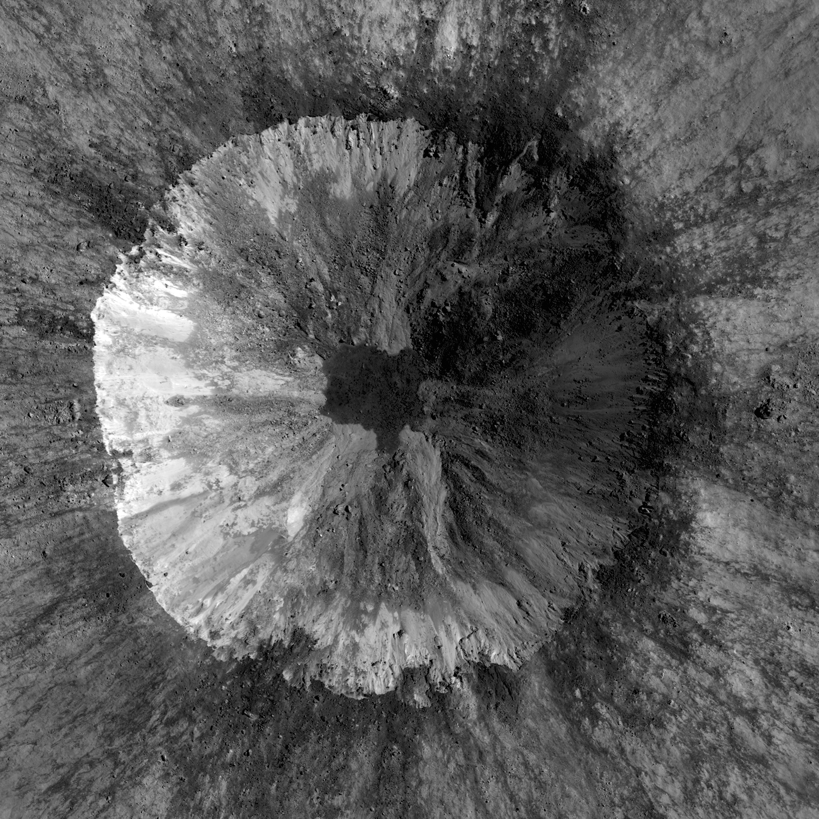
LROC Featured Images show off the incredible variety of stunning lunar geology imaged by the LROC NACs. While these beautiful images allow scientists to study the surface of the Moon with respect to morphologic detail and albedo variations at 0.5 meters per pixel, repeat - or stereo - images of the same location on the surface at similar illuminations but different viewing geometries provide scientists the chance to create a 3D topographic model. Why all the fuss? Well, these Digital Terrain Models, or DTMs, are critical to scientific investigations where topographic information about the lunar surface aids is necessary. Today's Featured Image is a DTM of a 2.3 km diameter unnamed impact crater (17.682°S, 144.408°E) west of Isaev crater. This impact crater is very young, evidenced by its high-reflectance ejecta blanket, and is of scientific interest because the interior crater morphology is complex (see image below).

LROC Narrow Angle Camera (NAC) mosaic of an unnamed 2.3 km diameter crater, one of the two NAC stereo pairs used to create the DTM represented in the LROC Featured Image released May 2, 2012. While your brain knows the crater is concave, a depression, because of illumination and shadowing, the NAC mosaic alone can't be used to determine the elevation change from rim to floor. Image from LROC the left and right coincident frames of LROC NAC observation M143683729, resampled to 2 meters per pixel resolution for the DTM, field of view is 3.2 km across. LRO orbit 6308, November 6, 2010; from 61 kilometers. View the larger LROC complementary image HERE [NASA/GSFC/Arizona State University].
The NAC mosaic above probably looks somewhat familiar because most Copernican-aged craters have crisp crater rims, prominent ejecta blankets, mass-wasting observed on the crater walls, and often times impact melt in pools on the crater floor or dark streamers superposed on the ejecta blanket. Over time, material from the rim and crater walls slumped toward the crater floor. Some of these slumps are composed of rockier, blockier material, while others do not have entrained rubble.

Full resolution (62.58 meters per pixel) detail from LROC Wide Angle Camera (WAC) observation M176690527C (604nm) shows the subject crater under mid-afternoon illumination (incidence 64.28°), LRO orbit 11174, November 23, 2011 from 48.8 kilometers. When comparing with the LROC QuickMap 6 x 6km topography at lower right we can see the 400 meter rise in elevation, from the crater floor to the selected area's terminus just to the northeast, witnessing how the complexity of terrain's elevation is not easily visible from overhead [NASA/GSFC/Arizona State University]
There is a low-reflectance impact melt deposit on the crater floor with irregular contacts with the crater wall materials. Impact melt ponds often exhibit a relatively smooth surface because as the liquid melt cools, it seeks an equipotential surface, which is flat. But how does a scientist quantify "smooth"? Looking at the NAC, there are some debris entrained in the melt, but overall the surface looks flat. However, simply because something "looks" a certain way does not mean it is!

Simulated oblique view west from 150 kilometers over the LROC Wide Angle Camera (WAC) monochrome 100 meter Global Mosaic spread upon LOLA altimetry (ILIADS Application, Lunar Mapping and Modeling Project). The Copernican Age crater highlighted in the LROC Featured Image released May 2, 2012 is the small crater with a bright ejecta blanket at bottom center. in the farside highlands - 450 kilometers east of the central peaks of mare-filled Tsiolkovskiy crater, visible at top center [NASA/GSFC/LMMP/Arizona State University].

DTMs derived from LROC NAC stereo images are extremely useful because DTMs provide quantitative measures to complement qualitative descriptions. For the case of determining the smoothness of the impact melt pond, the slope of the crater walls and floor deposit can be calculated using the DTM. At the scale shown above, 2 m/pixel, the impact melt deposit surface is all at the same elevation and can thus be considered to be smooth. Furthermore, DTMs sometimes reveal unexpected observations! In the full frame of the LROC NAC DTM, there is a region of lower elevation to the north of the unnamed crater and a region of higher elevation to the south; these regions are not easily discerned in the LROC NAC mosaic.

Take a look at the full LROC mosaics - (DTM and NAC) - and see how the morphology you observe in the NAC image is linked with the elevation you see in the DTM.

Discover the Moon using DTMs in the DTM RDR Archive, HERE.

Direct link to today's Featured Image DTM in the RDR Archive.

Related Posts:
Barnstorming Linné crater
A Digital Terrain Model of the Orientale Basin
Precise 3D Measurements of Objects at Apollo 14Landing Site from LROC NAC Stereo Images

Monday, February 13, 2012

Howard Fink takes a closer look at Hermite A

Howard Fink at New York University continues to make full sense of the hundreds of millions of laser altimetry data points measured by the LOLA instrument on board the Lunar Reconnaissance Orbiter since June 2009 [Howard Fink/NYU/NASA/GSFC/LOLA].
Joel Raupe

A lingering concern from those early, heady days of the Vision for Space Exploration, the initiative that set in motion the five spacecraft now orbiting the Moon, has been how to take full advantage of the unprecedented amount of data the precursor robotic spacecraft would return to Earth. This was true especially of LRO, a mission that broke the record for the sheer volume of information returned from deep space (from all previous missions combined). One answer emerging has proven to be crowd-sourcing.

The regular release of data in three month intervals has inspired many not professionally attached to the mission to assemble new global maps and montages. Even so, if the science still being pulled from the data record returned by the relatively modest Lunar Pioneer mission is used as a guide it's likely new discoveries about the Moon will still be being announced a least a decade after the LRO mission comes to an inevitable end.

One of those assembling lunar terrain models from LRO data is Howard Fink of New York University, in his case the LRO laser altimetry collected by the LOLA instrument - the most comprehensive of its kind.

Fink has just released a new and better model of Hermite A, a 22 kilometer-wide highland crater with an interior in permanent shadow not far from the Moon's north pole. That model can be viewed in detail at his Wordpress AstroPhoto blog, HERE.

In addition, "in tribute to all those who don't still have to look up how to spell its name," Fink released in February a remarkable look at Rozhdestvenskiy, HERE, in the context of the whole lunar pole region. Both can readily be compared with the data gleaned from the LROC Wide Angle Camera (WAC) derived elevation model, visible using the tools accompanying the LROC QuickMap, HERE.


Related Posts:
The replicators have arrived (November 7, 2011)
LOLA: Cold Hermite (April 10, 2011)
Lunar elevation models come in many forms (March 4, 2011)
LRO's unprecedented topography of the Moon (December 17, 2010)
LROC: The Lunar North Pole (October 5, 2010)
LRO Mini-RF spends month mapping lunar poles (August 8, 2010)
'Potentially ice-rich' crater in Rozhdestvenskiy (July 2, 2010)
Coldest Spot on the Moon (December 16, 2009)

Monday, November 21, 2011

Apollo Metric Camera maps completed

The final three Apollo "J" missions as planned were devoted to science, and each of their Service Modules were equipped with an array of equipment that remained in orbit as their surface expeditions were carried out. Mapping Metric and Panorama Cameras operated over the sunlit surface over multiple orbits as part of the Apollo 15, 16 and 17 missions. Film canisters for these cameras were retrieved in spacewalks during the long cruise home. Until recently, the orbital corridors under the orbital plain of these last missions were the most well-understood detailed portions of the lunar surface [NASA/Google Earth].
Dr. Terry Fong
Director, Intelligent Robotics Group
NASA Ames Research Center

It gives me great pleasure to announce the release of the "Apollo Zone" Digital Image Mosaic (DIM) and Digital Elevation Model (DEM). These maps cover approx. 18% of the Lunar surface at a resolution of 1024 pixels per degree (approx 30 m/pixel). The maps are the result of 3 years worth of work by the NASA Ames Intelligent Robotics Group (IRG) to align and process more than 4,000 images from the Apollo Metric Camera (AMC), which flew aboard Apollo 15, 16, and 17. The AMC images were provided by the Apollo Image Archive at Arizona State University.
To preview the "Apollo Zone" maps, download the following "KML" file for viewing in Google Earth:

http://byss.ndc.nasa.gov/stereopipeline/dataviz/apollo_metric.kml

Once you open that file in Google Earth you will have options to view these "Apollo Zone" maps overlaid on Google Earth's "Moon mode". The full maps (in GeoTIFF format with complete metadata) have also been uploaded to the Lunar Mapping and Modeling Project (LMMP) portal (http://lmmp.nasa.gov) and will soon be available for visualization and download via that site.

The "Apollo Zone" maps cover the following sites of interest: Apollo 15, Apollo 16, Alphonsus Crater, Rima Prinz, Aristarchus Plateau-2, Ina D Caldera, Sulpicius Gallus, Mare Crisium, Mare Smythii, King Crater, Tsiolkovskiy Crater, Aitken Crater, and half of Van de Graaf Crater.

The terrain model has an average vertical accuracy of 40 m/pixel and standard deviation of 37 m (compared to LOLA laser altimetry tracks). Over 46% of the covered surface has vertical errors lower than 25 m.

The "Apollo Zone" maps (image, elevation, hillside, colorshade, confidence and precision) were automatically generated using new computer vision algorithms developed by IRG:

 - robust statistical sub-pixel stereo correspondence
 - robust bundle adjustment and radiometric corrections for large-scale
   image mosaics
 - orbital camera position/orientation estimation using interest point
   extraction
 - photometric correction of exposure time, shadow removal and generation of
   seamless large-scale image mosaics.
 - photometric method for reconstructing lunar albedo
 - photoclinometric terrain reconstruction method that improves lunar
   DTM precision
 - statistical method for multiple stereo digital terrain model mosaicking
 - multi-view 3D terrain reconstruction
 - DTM / LOLA alignment and lidar / image matching

These algorithms have been released as NASA open-source (Ames Stereo Pipeline, Neo-Geography Toolkit, and NASA Vision Workbench). Map processing was performed using the NASA Pleiades supercomputer. In addition to the Apollo Metric Camera images, the fully automatic map processing pipeline has also been used with data from the Lunar Reconnaissance Orbiter Camera (LROC) and by several planetary science groups.

This work was funded by the Lunar Mapping and Modeling Project (LMMP). We gratefully acknowledge the support of our collaborators at NASA MSFC, NASA GSFC, JPL and USGS. We sincerely thank Mark Robinson and the Apollo Image Archive at ASU for restoring and bringing the AMC data to "digital life". Our special thanks go to Ray French and Mark Nall for their support and leadership of LMMP.

If you have any questions, or would like more information, please let me know.

Cheers,

Terry Fong

Wednesday, November 16, 2011

LROC's new Global Lunar Topography

Full hemisphere example of the newly released Lunar Reconnaissance Orbiter Camera (LROC) Wide Angle Camera (WAC) color-shaded relief of the lunar farside, derived from their global Digital Terrain Model. View the larger image accompanying their November 16 announcement, HERE [NASA/GSFC/DLR/Arizona State University].
Mark Robinson
Principal Investigator
Lunar Reconnaissance Orbiter Camera (LROC)
Arizona State University


Global topography -- a boon to lunar scientists and explorers around the world! Today the LROC team releases Version 1 of the Wide Angle Camera (WAC) topographic map of the Moon. This amazing map shows you the ups and downs over nearly the entire Moon, at a scale of 100 meters across the surface, and 20 meters or better vertically. Despite the diminutive size of the WAC (it fits in the palm of one's hand), it images nearly the entire Moon every month. Every month? Yes! Redundant data? No! Each month the Moon's lighting changes, so the WAC methodically builds up a record of how different rocks reflect light under different conditions, and adds to the LROC library of stereo observations. The WAC really is the little camera that could! It was built by Malin Space Science Systems (MSSS) in San Diego CA, and is very similar to another MSSS camera (MARCI) now in orbit around Mars.

Left: LROC Wide Angle Camera attached to a test setup shortly before mounting on the spacecraft. Right: WAC being handed up to engineers for integration with LRO. View the released image HERE (photos M. Robinson).
The WAC has a pixel scale of about 75 meters, and with an average altitude of 50 km, a WAC image swath is 70 km wide across the ground-track. Because the equatorial distance between orbits is about 30 km, there is nearly complete orbit-to-orbit stereo overlap all the way around the Moon, every month. Using digital photogrammetric techniques, a terrain model was computed from this stereo overlap. The new topographic model was constructed from 69,000 WAC stereo models. Due to persistent shadows near the poles it is not possible to create a complete WAC stereo map at the very highest latitudes. Fortunately, the LRO Lunar Orbiter Laser Altimeter (LOLA) excels at characterizing the topography of the poles. Since the LRO orbits converge at the poles and LOLA ranges to the surface with its own lasers, LOLA provides a very high resolution topographic model of the poles. This LOLA map can fill in the WAC "hole at the pole".

Detail from WAC topography model, shades of gray represent elevation. Darker values are lower terrain and brighter values are higher points. (Image center is near 19.1°N, 175.3°E) View the much larger demonstration image HERE [NASA/GSFC/DLR/Arizona State University].
How is a digital topographic map created from stereo images? The WAC stereo images were compared one against another by pattern-matching a moving box of pixels until the best fit was found between two images with different viewing angles. Best fit pixel positions are combined with the LRO orbit position and the WAC viewing angles to define two 3D rays (lines of sight). The intersection point of these rays defines the location and the elevation of the point on the surface. Since the correlation box is bigger than 100 meters, surface details at the 100-meter scale are not fully resolved in a single stereo pair. However, each 100 meter square has an average of 26 stereo points within it (for a planet-wide total of 100 billion points), which helps to sharpen the elevation estimate. The resolution, in a formal sense, is probably close to 300 meters, and the accuracy of the elevations is estimated to be about 10 to 20 meters. This new map is called the Global Lunar DTM 100 m topographic model, or “GLD100”,  and covers 79°S to 79°N latitudes, 98.2% of the entire lunar surface. The WAC topography was produced by LROC team members at the German Aerospace Center (DLR).

Color-shaded relief detail of the same region in the figure above. View the spectacularly detailed and larger release image HERE [NASA/GSFC/DLR/Arizona State University].
Shaded relief images can be created from the GLD100 by illuminating the surface from a given Sun direction and elevation above the horizon, and to convey an absolute sense of height the resulting grayscale pixels are painted with colors that represent the altitude. Visualizations like these allow scientists to view the surface from very different perspectives, providing a powerful tool for interpreting the geologic processes that have shaped the Moon
.
And the LROC WAC Global monochrome mosaic also corresponding to same area, with the accompanying larger and more detailed release image available HERE [NASA/GSFC/DLR/Arizona State University].
The large irregularly shaped Buys-Ballot crater, seen in the three images above, is about 47 km by 62 km. The WAC topography shows the flat floor to lie some 3100 meters below the western rim and 4600 m below the eastern rim. The central peak rises about 800 m above the floor. For comparison the width and depth of this crater are larger than those of the Grand Canyon, AZ.

Topographic profile (highly exaggerated) across Buys-Ballot crater, note the flat floor [NASA/GSFC/DLR/Arizona State University].

Why is the floor of the crater so flat? The WAC mosaic holds an important clue -- note how dark the floor is. On the Moon, dark (low albedo) material is typically basalt, which is dark because it is relatively rich in iron (mafic minerals). On the Moon, basalts are erupted as very hot lavas, making them very fluid, thus they tend to spread out and flood local topographic lows. From the topography and WAC image data, one can make a confident interpretation that the floor of this unusual crater is most likely flooded with basalt. But why such a small eruption? Most flood basalts on the nearside cover vast expanses of lunar terrain, but why not on the farside? Another mystery for future lunar explorers to unravel!

The area shown here is only a tiny portion of the Moon: see if you can find Buys-Ballot in the full resolution hemispheric view.

What improvements can be made over this first release of the LROC WAC GLD100? The current model incorporates the first year of stereo imaging, and there is another year of data that can be added to the solution. These additional stereo images will not only improve the sharpness (resolution) of the model but also fill in very small gaps that exist in the current map. The LROC team has made small improvements to the camera distortion model, and the LOLA team has improved our knowledge of the spacecraft position over time. These next generation steps will further improve the accuracy of Version 2 of the LROC GLD100 topographic model of the Moon.

Explore the new LROC GLD100!

And here are Direct links to color shaded relief visualizations (relatively large *.tif image files*):


Orthographic projection centered at 0° longitude and 0° latitude.
Orthographic projection centered at 60° longitude and 0° latitude.
Orthographic projection centered at 120° longitude and 0° latitude.
Orthographic projection centered at 180° longitude and 0° latitude.
Orthographic projection centered at 240° longitude and 0° latitude.
Orthographic projection centered at 300° longitude and 0° latitude.
Orthographic projection centered at 0° longitude and 90° latitude.
Orthographic projection centered at 0° longitude and -90° latitude.

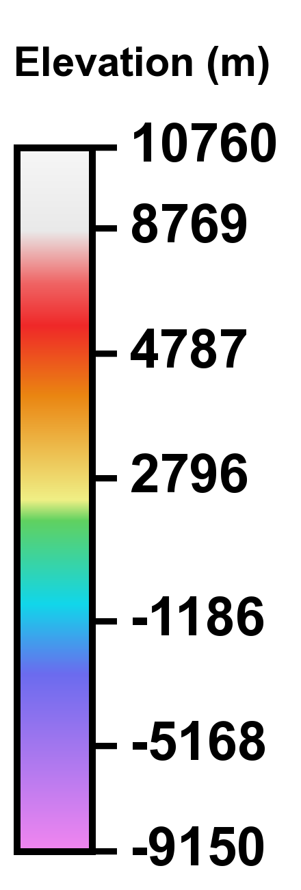
Color scale legend for LROC Color Shaded Relief
. View the full size graphic, HERE [NASA/ GSFC/ DLR/ Arizona State University].
*NOTE: OS X (and many other) users may prefer opening these large TIFF files directly within a browser. Please select and "Save" to local storage media, allowing the option of opening these files in an image viewer or editing program.

Monday, November 7, 2011

The replicators have arrived

"Slide show" comparing an illumination model of the lunar north pole region, made using a three-dimensional printer and LRO laser altimetry by Howard Fink of New York University, with standard representations of LOLA data and one LROC WAC mosaic [Howard Fink/NYU/NASA/GSFC/ASU].
Paul D. Spudis
The Once & Future Moon
Smithsonian Air & Space

Of all the wonders depicted in science fiction books and movies, one of the most intriguing is the machine that makes anything that you need or desire.  Merely enter a detailed plan, or push the button for items programmed into the machine – dials twirl, the machine hums and out pops what you requested.  Technology gives us Aladdin’s Lamp.  A handy device that will find many uses.

We’re not quite there yet but crude versions of such imagined machines already exist.  These machines are called “rapid prototype” generators or three-dimensional printers.  They take digitized information about the dimensions and shape of an object and use that data to control a fabricator that re-creates the object using a variety of different materials.  Typically, these machines use easy to mold plastics and epoxy resins but in principle, any material could be used to create virtually any object.

3-D printers contribute to the advancement our understanding of lunar morphology, as LRO fills long-neglected gaps in lunar morphology. Malapert Massif (85.9°S, 0.42°E). From an 80 meter resolution image of the South Pole region of the Moon built from a 20 meter original supplied by the LRO/LOLA science team [Howard Fink/NYU].
For comparison nearly the same area modeled by laser altimetry (LOLA) above, Malapert from the LROC Wide Angle Camera (WAC) RDR 100 meter Global Mosaic [NASA/GSFC/Arizona State University].

What’s the relevance of this technology to spaceflight and to the Moon?  One of the key objects of lunar return is to learn how to use the material and energy resources of the Moon to create new capabilities.  To date, we have focused our attention on simple raw materials like bulk regolith (soil) and the water found at the poles.  It makes sense to initially limit our resource utilization ambitions to simple materials that are both useful and relatively massive, which currently have those killer transportation costs when delivered from Earth.  Bulk regolith has many different uses, such as shielding (e.g., rocket exhaust blast berms) as well as raw material for simple surface structures.

However, once we are on the Moon and have met the basic necessities of life, we can begin to experiment with making and using more complex products.  In effect, the inhabitants of the Moon will begin to create more complicated parts and items from what they find around them, just outside their door.  The techniques of three-dimensional printing will allow us to discover what makes life off-planet easier and more productive.  We will experiment by using the local materials to maintain and repair equipment, build new structures, and finally begin off-planet manufacturing.

To illustrate the obliquity of the view angle and the problem posed in gathering information about the tantalizing but permanently shadowed regions of the Moon, Shackleton crater, with the Moon's South Pole on its rim (upper left) together with Malapert Massif on the horizon, seen with Earth as a back drop. HDTV still from Japan's Kaguya orbiter released November 2007 [JAXA/NHK/SELENE].
During the early stages of lunar habitation, material and equipment will be brought from Earth.  With continued use, particularly in the harsh lunar surface environment, breakdowns will occur.  Although initially we will use spare parts from Earth, for simple uncomplicated structures that are needed quickly, a three-dimensional printer can make substitute parts using local resource materials found near the outpost.  Most existing 3-D printers on Earth use plastics and related materials (which are complex carbon-based compounds, mostly derived from petroleum) but some processing has used concrete, which can be made on the Moon from sieved regolith and water.  In addition, we also know that regolith can be fused into ceramic using microwaves, so rapid prototyping activities on the Moon may eventually find that partially melting particulate matter into glass is another way to create useful objects.

The lunar surface is a good source of material and energy useful in creating a wide variety of objects.  I mentioned simple ceramics and aggregates, but additionally, a variety of metals (including iron, aluminum and titanium) are available on the Moon.  Silicon for making electronic components and solar cells is abundant on the Moon.  Designs for robotic rovers that literally fuse the in-place upper surface of the lunar regolith into electricity-producing solar cells have already been imagined and prototyped.  We can outsource solar energy jobs to the Moon!

These technical developments lead to mind-boggling possibilities.  Back in the 1940s, the mathematician John von Neumann imagined what he called “self-replicating automata,” small machines that could process information to reproduce themselves at exponential rates.  Interestingly, von Neumann himself thought of the idea of using such automata in space, where both energy and materials are (quite literally) unlimited.  A machine that contains the information and the ability to reproduce itself may ultimately be the tool humanity needs to “conquer” space.  Hordes of reproducing robots could prepare a planet for colonization as well as providing safe havens and habitats.

We can experiment on the Moon with self-replicating machines because it contains the necessary material and energy resources.  Of course, in the near-term, we will simply use this new technology to create spare parts and perhaps simple objects that we find serve our immediate and utilitarian needs.  But things like this have a habit of evolving far beyond their initial envisioned use, and often in directions that we do not expect; we are not smart enough to imagine what we don’t know.  The technology of three-dimensional printing will make the habitation of the Moon – our nearest neighbor in space – easier and more productive.  Even now, creative former NASA workers have found a way to make this technology pay off.  In the future, perhaps their talents could be applied to making the Moon a second home to humanity.

Originally published October 24, 2011 at his Smithsonian Air & Space blog The Once and Future Moon, Dr. Spudis is a Senior Staff Scientist at the Lunar and Planetary Institute in Houston. The opinions expressed are those of the author and are better informed than average.

Friday, December 17, 2010

LRO's unprecedented topography of the Moon


The rugged South Pole, revealed through LOLA's millions of laser hits centered on prominent (if small, at only 10 kilometers) Shackleton. The jagged ancient rim of South Pole-Aitken (SPA) Basin, it's smaller near side component to the north of Malapert (center top) and the fantastically high Liebnitz beta massifs. To their left Cabeus hides the highest concentrations of water while some of the other permanently-shadowed areas do and others mysteriously do not hold such promise [NASA/GSFC/MIT/SVS].

Nancy N. Jones
Goddard Space Flight Center

NASA's Lunar Reconnaissance Orbiter is allowing researchers to create the most precise and complete map to date of the moon's complex, heavily cratered landscape.


LOLA topographic map centered on the Apollo 15 landing site, highlighting the Apennine and Caucasus ranges and the fairly subtle wrinkling in Serenitatis. The false colors indicate elevation: red areas are highest and blue lowest [NASA/GSFC/MIT/SVS].

"This dataset is being used to make digital elevation and terrain maps that will be a fundamental reference for future scientific and human exploration missions to the moon," said Dr. Gregory Neumann of NASA's Goddard Space Flight Center in Greenbelt, Md. "After about one year taking data, we already have nearly 3 billion data points from the Lunar Orbiter Laser Altimeter on board the LRO spacecraft, with near-uniform longitudinal coverage. We expect to continue to make measurements at this rate through the next two years of the science phase of the mission and beyond. Near the poles, we expect to provide near-GPS-like navigational capability as coverage is denser due to the spacecraft's polar orbit." Neumann will present the map at the American Geophysical Union meeting in San Francisco December 17.

The Lunar Orbiter Laser Altimeter (LOLA) works by propagating a single laser pulse through a Diffractive Optical Element that splits it into five beams. These beams then strike and are backscattered from the lunar surface. From the return pulse, the LOLA electronics determines the time of flight which, accounting for the speed of light, provides a precise measurement of the range from the spacecraft to the lunar surface. Range measurements, combined with accurate tracking of the spacecraft's location, are used to build a map revealing the contours of the lunar landscape. The five beams create a two-dimensional spot pattern that unambiguously reveals slopes. LOLA will also measure the spreading of the return pulse to get the surface roughness and the change in the transmitted compared to the return energy of the pulse to determine surface reflectance.


The "resource-rich" lunar North, triangulated by Hermite on the right, where the Solar System's coldest temperatures have been recorded, wide-spread Rozhdestvenskiy across the top and Perry, bottom right, hugging the North Pole along with recently-designated Whipple [NASA/GSFC/MIT/SVS].

The new LOLA maps are more accurate and sample more places on the lunar surface than any available before. "The positional errors of image mosaics of the lunar far side, where direct spacecraft tracking – the most accurate -- is unavailable, have been one to ten kilometers (about 0.62 to 6.2 miles)," said Neumann. "We're beating these down to the level of 30 meters (almost 100 feet) or less spatially and one meter (almost 3.3 feet) vertically. At the poles, where illumination rarely provides more than a glimpse of the topography below the crater peaks, we found systematic horizontal errors of hundreds of meters (hundreds of yards) as well." In terms of coverage, the nearly three billion range measurements so far by LRO compare to about eight million to nine million each from three recent international lunar missions, according to Neumann. "They were limited to a mile or so between individual data points, whereas our measurements are spaced about 57 meters (about 187 feet) apart in five adjacent tracks separated by about 15 meters (almost 50 feet)."

"Recent papers have clarified some aspects of lunar processes based solely on the more precise topography provided by the new LOLA maps," adds Neumann, "such as lunar crater density and resurfacing by impacts, or the formation of multi-ring basins."

"The LOLA data also allow us to define the current and historical illumination environment on the moon," said Neumann. Lunar illumination history is important for discovering areas that have been shaded for long periods. Such places, typically in deep craters near the lunar poles, act like cold storage, and are capable of accumulating and preserving volatile material like water ice.

The landscape in polar craters is mysterious because their depths are often in shadow. The new LOLA dataset is illuminating details of their topography for the first time. "Until LRO and the recent Japanese Kaguya mission, we had no idea of what the extremes of polar crater slopes were," said Neumann. "Now, we find slopes of 36 degrees over several kilometers (several thousands of yards) in Shackleton crater, for example, which would make traverses quite difficult and apparently causes landslides. The LOLA measurements of shadowed polar crater slopes and their surface roughness take place at scales from lander size to kilometers. These measurements are helping the LRO science team model the thermal environment of these craters, and team members are developing temperature maps of them."

LRO and LOLA were built and are managed by NASA Goddard. The research was funded by NASA's Exploration Systems Mission Directorate at NASA Headquarters in Washington.

Thursday, March 4, 2010

Lunar elevation models come in many forms

Howard Fink has a gift for Charles Wood (LPOD). One of four cast models of the Hadley Rille Delta, landing site of Apollo 15 and, for many years, the topography of the lunar surface best surveyed from lunar orbit by laser altimetry (>10 million points). At top is a close-up of the cast on the lower right, tweaked for detail. At middle is a glance at the same area as seen in Google Moon from a slightly different angle for context. That scene is overlaid with Apollo, LROC and Chandrayaan Mini-SAR data. And below are each of the four casts by Howard. For a full-size view, he has uploaded that image to his website HERE. For more information and detailed views of the work, see Apollo 15 landing site in 3-D.

Wednesday, December 2, 2009

Chang'E-1 has blazed a new trail in China's deep space exploration

Lunar global topographic map based on Chang'E-1 Digital Elevation model (DEM) CLTM-s01.

Science in China
(Series G, Physics, Mechanics & Astronomy)

A huge amount of scientific data have been accumulated by the Chang'E-1 lunar orbiter. Using laser altimeter data, Jinsong Ping and Qian Huang et al obtained improved 3D lunar topography, and based on this, they had made new discoveries (such as impact basins and volcanic deposit highlands) of some ancient topographic characteristics on the lunar surface. Chao Chen and Qing Liang et al., found the South Pole-Aitken (SPA) Basin as the biggest mascon on the moon and put forward a fault structure hypothesis for the Apenninus Mountains, which is significant for the study of the origin and evolution of the moon.

The above special-issue papers reporting on the Chang'E selenodesy results were jointly accomplished by experts from the Shanghai Astronomical Observatory (SHAO), the China University of Geosciences (Wuhan) and other institutions. They will appear on Vol. 39 Issue 10 of the "Science in China Series G: Physics, Mechanics & Astronomy" and Vol. 54 Issue 20 of the Chinese Science Bulletin.

Since the 1990s, there has been a new worldwide upsurge of lunar exploration missions. As did the other lunar spacecrafts launched about the same time frame, the Chang'E-1 lunar orbiter focused on selenodesy so that it could remedy the low resolution and poor coverage problems of past data and open the door to recovering lunar evolution by detecting new lunar topography, gravity fields or interior structures. Furthermore, it would prepare for future Chinese spacecraft landing on the surface of the moon.

Lunar topography, chemical composition and thickness all show obvious dichotomy. In-depth investigation into the lunar dichotomy and characteristics of basins, mascons, impact craters and volcanic highlands is the only way to throw light on the history of lunar evolution. Based on the Chang'E-1 lunar DEM model CLTM-s01 published in 2008, researchers from SHAO took a comparative planetary science approach and successfully found some impact basins (i.e. the quasi-impact basin Sternfeld-Lewis and impact basin Fitzgerald-Jackson) and one crater (i.e. the crater Wugang) on the Far Side, and one middle scale volcanic deposit highland (i.e. the 2.8 km highland Yutu) on the Near Side. Moreover, they analyzed and identified some middle scale impact basins and classified them according to their circular characteristics.

Based on the Bouguer gravity anomaly, researchers from the China University of Geosciences confirmed the SPA basin is the biggest mascon on the terrestrial planets in the solar system. Comparing the Apenninus Mountain of the moon with the Himalayas on Earth, they put forward a hypothesis about the possible existence of a big fault structure band, which would possibly change our previous knowledge that there is no motion in the interior of the moon.

Due to certain operational limitations, it is difficult to calibrate the data collected by the Chang'E-1 orbiter. The researchers tried to get around various problems with novel techniques (especially related to the interferometer spectrometer imager), and made the previously inapplicable data useful for estimating the distribution of lunar materials. Besides, Chinese astronomers creatively monitored the critical arcs of the Chang'E-1 trajectory with a VLBI measurement platform.

As forward-looking technologists, they also performed open-loop radiometric tracking of the spacecraft and other unprecedented test experiments, while further participating in same-beam observation of the Japanese SELENE spacecrafts. We believe these pioneering works would make a significant contribution to our country's future deep space exploration.

Friday, May 29, 2009

Spectacular new refinements to Kaguya laser altimeter maps have been released

Cropped to a much larger scale, just part of what was "terra incognita" of the lunar South Pole region of the Moon, from Earth's line of sight behind Malapert Mountain (center top, at 86 degrees south), the rim of South Pole Aitken Basin, most of which resides on the Far Side, and Shackleton, where Near Side longitudinal lines converge at 90 degrees South. Among other firsts Japan's first lunar orbiter, Kaguya (SELENE I) mapped the depths of permanently shaded Craters, likely cold traps for scarce volatiles, and even vitually-imaged the interior of Shackleton. All in all JAXA, and the other first-time lunar orbiters of ISRO and CNSA, have set quite an impressive standard for NASA's Lunar Reconassaince Orbiter (LRO) to surpass, after finally beginning its mission next month. JAXA released this astounding third refinement of Kaguya's laser altimeter topography May 28.

Kaguya Topography v. 3.5 far surpasses two earlier releases

Once again I'm in debt to Chuck Wood at Lunar Picture of the Day (LPOD). This time for alerting us to an update to the Kaguya (SELENE) Image Gallery, as always on the Japanese language site weeks before the same updates eventually make it to the English side of JAXA's tantalizing gallery.

It's not another HDTV image. It's a welcome third updated topography formulated from Kaguya's laser altimeter data gathered before its primary mission ended last December.

The first planet wide map was necessarily a little disappointing, of such large scale as to be exacting but of poorer resolution than the famous painted National Geographic wall map first released in March 1970, now hanging on my wall.

The second provided far greater detail and was made available in an appropriately huge .tiff file, ans representing data refined and many millions of data points. It was followed up with different projections showing definitive proof of Japan having located both the Moon's highest and lowest elevations. It's lowest was already known to be within the ancient South Pole-Aitken (SPA) Basin, easily seen affecting the shape of the Moon's backside in beautifully projected clarity. And its highest elevation was not very far away, also on the Far Side, on the rim of Korolev, within a formation that, taken on the whole, might well be part of the outer rim of a "Mega-Basin impact event" predating SPA, perhaps even centered near the northwestern edge of Mare Tranquilitais and larger than the entire Near Side of the Moon.

As excitement grows over the hopefully pending launch of the Lunar Reconnaissance Orbiter (LRO) with its companion mission the LCROSS impactor with its sensing shepherding vehicle, news arrived that JAXA had set a date for deorbitng Kaguya, near Gill Crater on June 10, only a week before an Atlas V carries the LRO/LCROSS bus to orbit and Trans Lunar Injection. to begin their long tours.

This has distracted those of us who regularly check Kaguya's Japanese language Flash Gallery for early releases, but Chuck Wood kept his eye on the Ball. JAXA has now released more laser altimeter data in an even more refined was, enough image and data to require a large Adobe pdf. format.

What a beauty, all 13.8 megabytes of it, layered much like those long available from the Planetary Data System and the Lunar and Planetary Science Institute. It represents even further improvements on what Chuch Wood admits are presently the best topographic maps of the Moon ever made.

Since the end of it primary mission at the end of 2008, after more than a year orbiting the Moon at around 100 kilometers in altitude, Kaguya has been lowered to as close as 15 kilometers in perilune, where JAXA investigators announced hopes to improve on magnetometer data and our understanding of the lunar morphology refinded from the 1998-1999 Lunar Prospector mission, most of it decyphered after that amazing and relatively cheap orbiter was itself "deorbited" ot far from the Moon's South Pole in 1999.

Work by Halekas, Hood, and many, many others have since continued to refine Prospector's returned data and mapped in crustal magnetism, e.g., at Descartes and Gerasimov, sufficiently intense to stand-off solar wind, miniature bowshocks whose longevity, along that of their associated surface albedos, continues to baffle.

Kaguya, like India's Chandrayaan, provided us with a hint of how we can expect data to be delivered from LRO during the next year and beyond.

Corrections and refinements will improve upon early results, after much more work.

Meanwhile, we are also promised real-time availability of HiRes camera imagery, in much the same manner images from Cassini and the rovers Opportunity and Spirit, which should provide for plenty to digest while professionals create the kinds of product that will undoubtedly raise as many question as are answered, and past the life-time of the vehicle, just the camera-less Lunar Prospector continues to surprise, through hard work, a decade after its impact.

Kaguya has refined the long-elusive center of gravity of the Moon down to within two or three meters, and mapped the compex gravity to a resolution never seen.

Kaguya has found, with precision, the lowest elevations (within South Pole Aitken Basin) and the Moon's highest (near on the rim of Korolov) and these are are also pinpointed, on this new map, as are the locations of each of the Apollo landing sites.

In the context of all the other data examine in both Kaguya's and soon LRO's laser altimeter data, that cluster of landing sites is a stark seen as proof of how much of Earth's Moon was left unexplored at the cancelling of Apollo.

Add to the new and skillful refinements to Apollo orbital photography and mini-satellite data being painstakingly restored today, and the exceptional new information being tweeked from the forty-year-old Lunar Orbiter data, it is probably safe to say that, beginning with the humble Prospector the DOD's Clementine sensor experiments, we have learned, and are learning, more about the Moon today than at any time since the Apollo Era.