Showing posts with label LROC DEM. Show all posts

Tuesday, December 11, 2012

Impact melt in Picard crater

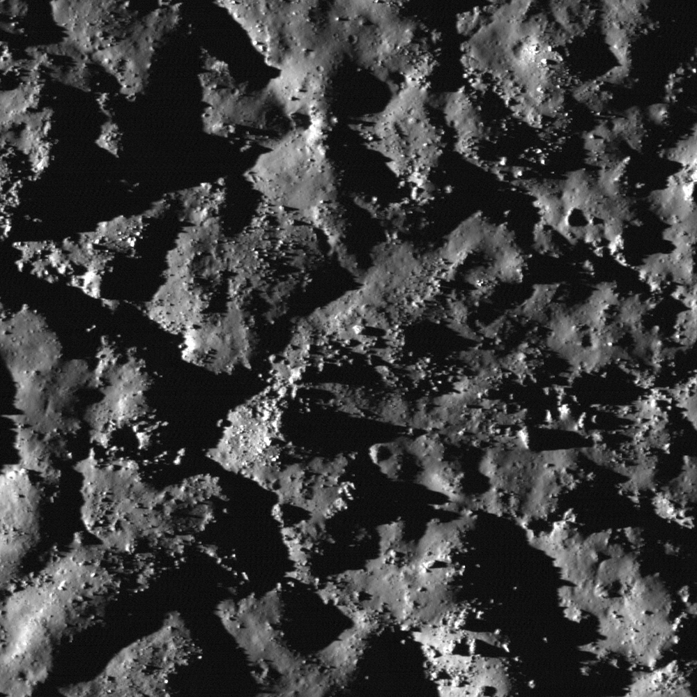
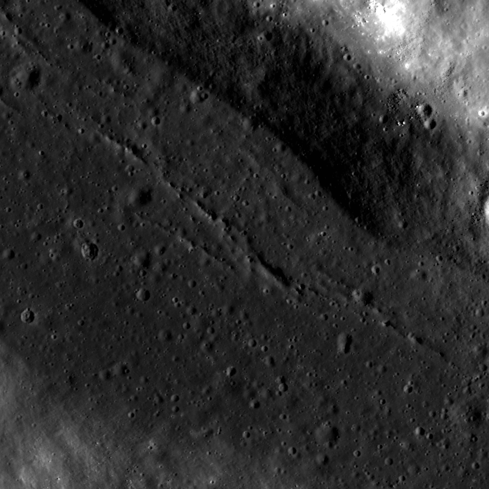
Cracks in ancient impact melt, pooled on a terrace on the wall of Picard, a landmark crater on the basin floor of Mare Crisium. The cracks probably formed during cooling, as the impact melt solidified. LROC Narrow Angle Camera (NAC) M1107917713RE, LRO orbit 15556, November 18, 2012; field of view approximately 1300 meters [NASA/GSFC/Arizona State University].
Drew Enns
LROC News System

Craters inform lunar scientists about many aspects of the Moon's surface and subsurface. Impact craters act as drill holes into the lunar subsurface, excavating deep material and scattering this previously buried material into their ejecta blankets. Impact melt within craters preserves a mix of the material that was excavated as well. Picard crater, at 14.55° N, 54.74° E, exposes a chemically distinct underlying basalt layer in Mare Crisium. In this way, Picard crater contributed to our understanding of the volcanic stratigraphy within the depths of the Mare Crisium basaltic fill. Does Picard crater penetrate through the basalts to expose the underlying highlands material, and can the impact melt help us understand more about the stratigraphy of the Mare Crisium?

Wide contextual view of the interior wall of Picard, from LROC NAC M1107917713R [NASA/GSFC/Arizona State University].
LROC Wide Angle Camera (WAC) context image of 22.34 km-wide Picard. Monochrome (643nm) mosaic of LROC WAC M150158282C and M150165076C (orbit 7264 and 7265, January 20, 2011; resolution 57.3 meters [NASA/GSFC/Arizona State University].

The floor of Picard crater is relatively bright compared to the surrounding basalts (Head et al., 1978) making it likely the deepest material brought up was from benath the mare fill. Thus we can estimate the thickness of the basalt deposit at this location. Spectroscopic studies in the 90's found evidence of both a basaltic and highland rock signature within Picard crater (Blewett et al., 1995). The impact melt that fills a significant portion of Picard crater (like the terrace above) is likely a mix of both rock types, giving Picard crater this mixed signature. Using the LROC WAC Digital Elevation Model (DEM) for the area tells us that Picard crater's floor is about 2300 m below the surface, as is the thickness of the Mare Crisium basalt!

Explore more of Picard crater in the full LROC NAC, HERE.

Wednesday, May 2, 2012

LROC NAC DTM: Copernican crater in 3D

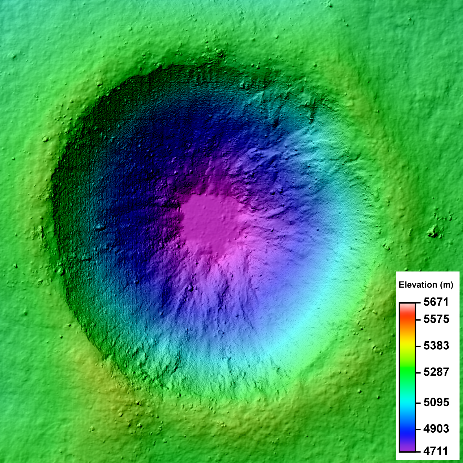
LROC Narrow Angle Camera (NAC) Digital Terrain Model (DTM) of an unnamed crater in the farside lunar highlands. Image field of view 3.2 km across. See the much larger (1600px) LROC Featured Image HERE [NASA/GSFC/Arizona State University].
Lillian Ostrach
LROC News System

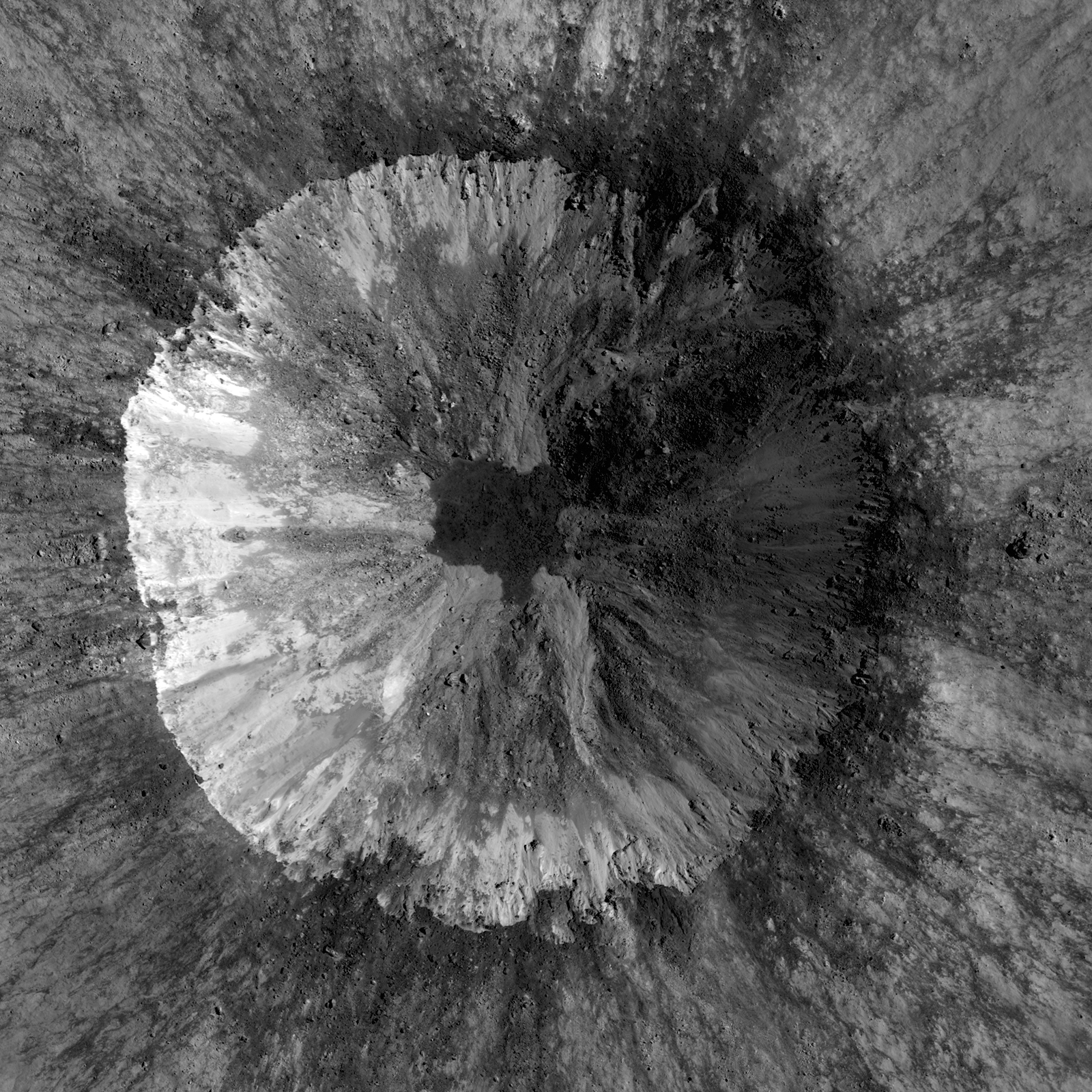
LROC Featured Images show off the incredible variety of stunning lunar geology imaged by the LROC NACs. While these beautiful images allow scientists to study the surface of the Moon with respect to morphologic detail and albedo variations at 0.5 meters per pixel, repeat - or stereo - images of the same location on the surface at similar illuminations but different viewing geometries provide scientists the chance to create a 3D topographic model. Why all the fuss? Well, these Digital Terrain Models, or DTMs, are critical to scientific investigations where topographic information about the lunar surface aids is necessary. Today's Featured Image is a DTM of a 2.3 km diameter unnamed impact crater (17.682°S, 144.408°E) west of Isaev crater. This impact crater is very young, evidenced by its high-reflectance ejecta blanket, and is of scientific interest because the interior crater morphology is complex (see image below).

LROC Narrow Angle Camera (NAC) mosaic of an unnamed 2.3 km diameter crater, one of the two NAC stereo pairs used to create the DTM represented in the LROC Featured Image released May 2, 2012. While your brain knows the crater is concave, a depression, because of illumination and shadowing, the NAC mosaic alone can't be used to determine the elevation change from rim to floor. Image from LROC the left and right coincident frames of LROC NAC observation M143683729, resampled to 2 meters per pixel resolution for the DTM, field of view is 3.2 km across. LRO orbit 6308, November 6, 2010; from 61 kilometers. View the larger LROC complementary image HERE [NASA/GSFC/Arizona State University].
The NAC mosaic above probably looks somewhat familiar because most Copernican-aged craters have crisp crater rims, prominent ejecta blankets, mass-wasting observed on the crater walls, and often times impact melt in pools on the crater floor or dark streamers superposed on the ejecta blanket. Over time, material from the rim and crater walls slumped toward the crater floor. Some of these slumps are composed of rockier, blockier material, while others do not have entrained rubble.

Full resolution (62.58 meters per pixel) detail from LROC Wide Angle Camera (WAC) observation M176690527C (604nm) shows the subject crater under mid-afternoon illumination (incidence 64.28°), LRO orbit 11174, November 23, 2011 from 48.8 kilometers. When comparing with the LROC QuickMap 6 x 6km topography at lower right we can see the 400 meter rise in elevation, from the crater floor to the selected area's terminus just to the northeast, witnessing how the complexity of terrain's elevation is not easily visible from overhead [NASA/GSFC/Arizona State University]
There is a low-reflectance impact melt deposit on the crater floor with irregular contacts with the crater wall materials. Impact melt ponds often exhibit a relatively smooth surface because as the liquid melt cools, it seeks an equipotential surface, which is flat. But how does a scientist quantify "smooth"? Looking at the NAC, there are some debris entrained in the melt, but overall the surface looks flat. However, simply because something "looks" a certain way does not mean it is!

Simulated oblique view west from 150 kilometers over the LROC Wide Angle Camera (WAC) monochrome 100 meter Global Mosaic spread upon LOLA altimetry (ILIADS Application, Lunar Mapping and Modeling Project). The Copernican Age crater highlighted in the LROC Featured Image released May 2, 2012 is the small crater with a bright ejecta blanket at bottom center. in the farside highlands - 450 kilometers east of the central peaks of mare-filled Tsiolkovskiy crater, visible at top center [NASA/GSFC/LMMP/Arizona State University].

DTMs derived from LROC NAC stereo images are extremely useful because DTMs provide quantitative measures to complement qualitative descriptions. For the case of determining the smoothness of the impact melt pond, the slope of the crater walls and floor deposit can be calculated using the DTM. At the scale shown above, 2 m/pixel, the impact melt deposit surface is all at the same elevation and can thus be considered to be smooth. Furthermore, DTMs sometimes reveal unexpected observations! In the full frame of the LROC NAC DTM, there is a region of lower elevation to the north of the unnamed crater and a region of higher elevation to the south; these regions are not easily discerned in the LROC NAC mosaic.

Take a look at the full LROC mosaics - (DTM and NAC) - and see how the morphology you observe in the NAC image is linked with the elevation you see in the DTM.

Discover the Moon using DTMs in the DTM RDR Archive, HERE.

Direct link to today's Featured Image DTM in the RDR Archive.

Related Posts:
Barnstorming Linné crater
A Digital Terrain Model of the Orientale Basin
Precise 3D Measurements of Objects at Apollo 14Landing Site from LROC NAC Stereo Images

Sunday, June 19, 2011

Tycho's chaotic crater floor


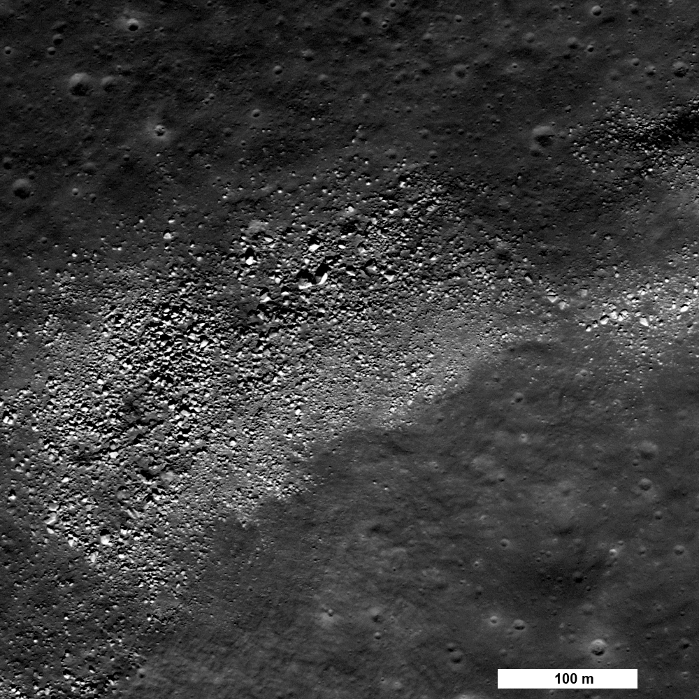
The floor of Tycho crater is covered in many places by a chaotic surface of impact melt forms. Image scale is 0.5 m/pixel, image width is 500m. Incidence angle 84°, LROC Narrow Angle Camera (NAC) observation M117568330R, LRO orbit 2459, January 9, 2010. View the full-size LROC Featured Image HERE [NASA/GSFC/Arizona State University].

Hiroyuki Sato
LROC News System

The interior floor of Tycho is covered by blocks, boulders and impact melt textures. The impact melt deposits often show networks of fractures visible at the LROC Wide Angle Camera pixel scale of 100 meters.

At Narrow Angle Camera resolution with very illumination incidence angles (illuminated almost along the horizon), the extremely complicated and chaotic nature of the surface is striking.


Simulated view of Tycho's chaotic interior floor from high upon the craters sharp central peaks looking toward the southwestern rim beyond, from a still lifted from the magnificent Kaguya Terrain Camera panorama video, offering an breathtaking tour of Tycho's anatomy, released May 27, 2009 [JAXA/SELENE].

Impact melts have extremely complicated thermal histories. When the impacting meteoroid's kinetic energy is large enough, the initial temperature of an impact melt can be much higher than that of normal magma, which is driven by volcanic activity. The melts are mixed together with ejecta debris, flow down slopes and puddle; loosing heat and increasing in viscosity with time. Once settled in the crater floor, solidification starts at the top and the bottom (chilled margins), and continues little by little to the melt volume interior. Any kind of deformation during this time (for example, the isostatic rebound of the crater floor, uneven thermal contraction, or late flows pushing pre-existing melts) will disturb the solidifying melt surfaces to make the chaotic patterns and sometimes cause local "eruptions" of melt onto the newly solid layer.


LROC Wide Angle Camera (WAC) 100 meter/pixel mosaic of Tycho impact crater cavity, overlayed by WAC color Digital Terrain Model (DTM) 500 meter/pixel (DLR, Germany). Image center is about 43.32°S, 348.89°E. Blue rectangle and yellow star indicate the locations of the NAC M117568330R frame and the LROC Featured Image, June 15, 2011. See the full-sized context image HERE [NASA/GSFC/Arizona State University].

Explore the extremely chaotic melt surface in the full NAC frame!

The topographic color was produced as a by-product of stereo analysis of the WAC global dataset. Producing the global Digital Elevation Model (DEM) is a big job being led by LROC team members at the German Aerospace Center (DLR; English version) in Berlin.


Yuri Goryachko and friends at Astronominsk are among the premier lunar (and planetary) photographers on Earth. The image above, from a mosaic captured April 6, 2009, offers an enhanced color view of Tycho, the crater who's wide-ranging ray system dominates the Moon's southern hemisphere and beyond as seen with the naked eye. Tycho is not an unusual crater by any standard. It's rays and rough hewn appearance are indicative of its relative youth, only 109 million years old - and not yet "optically darkened" by the relentless bombardment of meteors, micrometerors and hard radiation that gardens and changes the composition of the Moon's immediate surface (and albedo) every 2 million years or so [ASTONOMINSK].

Related posts:
Rubble Pile on Fresh Crater Floor
Mounds in a melt pond
Impact melt features in Tycho crater's floor
More Impact Melt!

Saturday, March 12, 2011

Farside & LROC WAC views all the way around!

Updated 0158 UT 16 March 2011
From LROC Wide Angle Camera Collection -
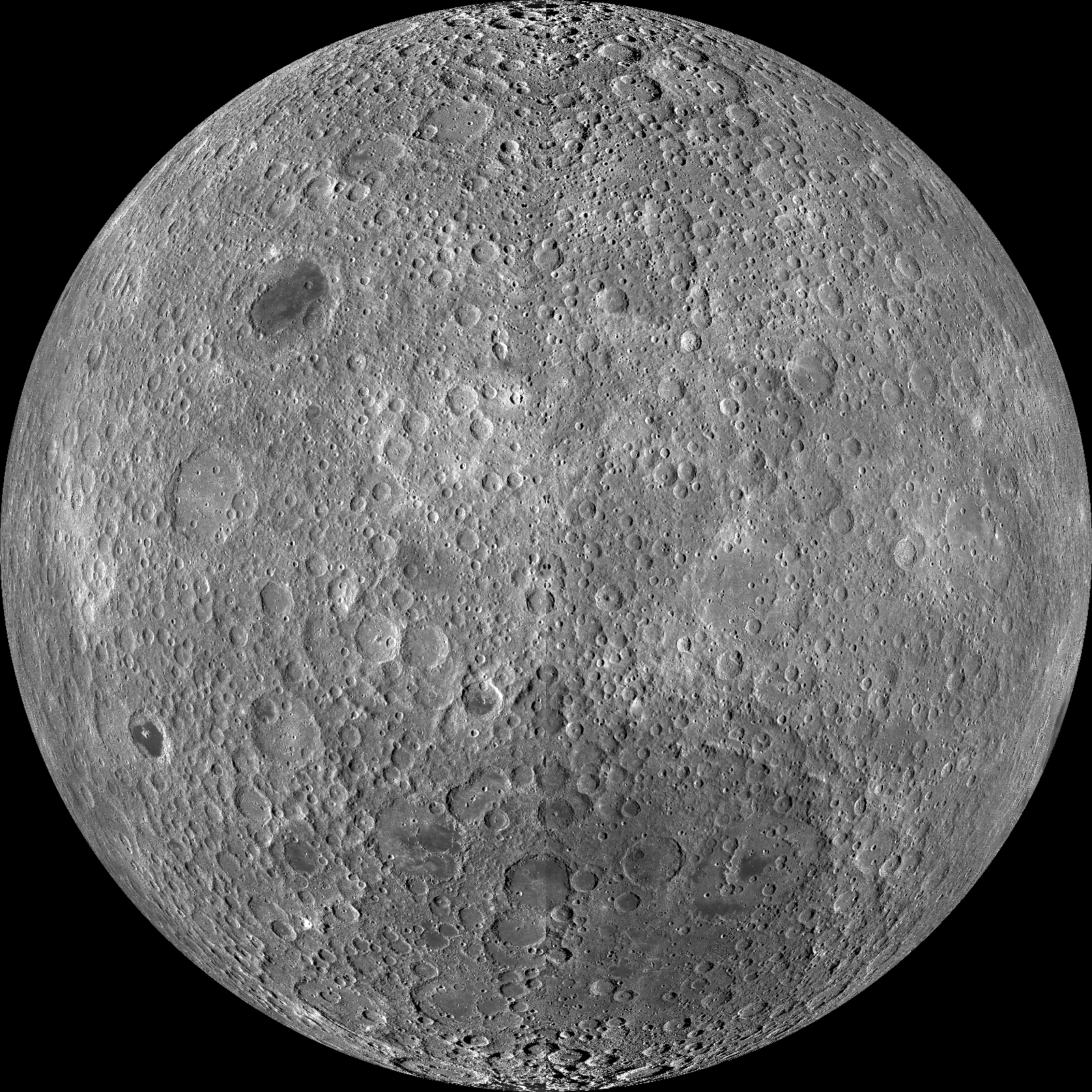
The lunar farside as never seen before. LROC Wide Angle Camera orthographic projection, centered at 0°N, 180°E. The Lunar Reconnaissance Orbiter Camera (LROC) team has now released a complete compliment of 100 meter resolution, contiguous illumination mosaics from a perspective over the Moon's equator. The full-sized (1600 x 1600) image is available HERE [NASA/GSFC/Arizona State University].

Mark Robinson
Principal Investigator
Lunar Reconnaissance Orbiter Camera
Arizona State University


Because the Moon is tidally locked, it was not until 1959 that the farside was first imaged by the Soviet Luna 3 spacecraft (hence the Russian names for prominent farside features, such as Mare Moscoviense).

And what a surprise -­ unlike the widespread maria on the nearside, basaltic volcanism was restricted to a relatively few, smaller regions on the farside, and the battered highlands crust dominated.

A different world from what we see from Earth.

Of course, the cause of the farside/nearside asymmetry is an interesting scientific question. Past studies have shown that the crust on the farside is thicker, likely making it more difficult for magmas to erupt on the surface, limiting the amount of farside mare basalts. Why is the farside crust thicker? That is still up for debate, and in fact several presentations at this week's Lunar and Planetary Science Conference attempt to answer this question.

The Clementine (1994) mission obtained beautiful mosaics with the sun high in the sky (low phase angles), but did not have the opportunity to observe the farside at sun angles favorable for seeing surface topography. This WAC mosaic provides the most complete look at the morphology of the farside to date, and will provide a valuable resource for the scientific community. And it's simply a spectacular sight!

The Lunar Reconnaissance Orbiter Camera (LROC) Wide Angle Camera (WAC) is a push-frame camera that captures seven color bands (321, 360, 415, 566, 604, 643, and 689 nm) with a 57-km swath (105-km swath in monochrome mode) from a 50 km orbit.

One of the primary objectives of LROC is to provide a global 100 m/pixel monochrome (643 nm) base map with incidence angles between 55°-70° at the equator, lighting that is favorable for morphological interpretations. Each month, the WAC provides nearly complete coverage of the Moon under unique lighting. As an added bonus, the orbit-to-orbit image overlap provides stereo coverage.

Reducing all these stereo images into a global topographic map is a big job, and is being led by LROC Team Members from the German Aerospace Center (Deutsches Zentrum für Luft- und Raumfahrt; DLR). Several preliminary WAC topographic products have appeared in LROC featured images over the past year (Orientale basin, Sinus Iridum).


For a sneak preview of the WAC global Digital Elevation Model (DEM) with the WAC global mosaic, view a rotating composite Moon (Full Resolution), HERE. The WAC topographic dataset will be completed and released later this year.

The global mosaic released today is comprised of over 15,000 WAC images acquired between November 2009 and February 2011. The non-polar images were map projected onto the GLD100 shape model (WAC derived 100 m/pixel Digital Terrain Model - DTM), while polar images were map-projected on the LOLA shape model. In addition, the LOLA derived crossover corrected ephemeris, and an improved camera pointing, provide accurate positioning (better than 100 m) of each WAC image.


As part of (their) March 2011 release to the Planetary Data System (PDS), the LROC team posted the global map in ten regional tiles. Eight of the tiles are equirectangular projections that encompass 60° latitude by 90° longitude. In addition, two polar stereographic projections are available for each pole from ±60° to the pole. These reduced data records (RDR) products will be available for download on March 15, 2011.

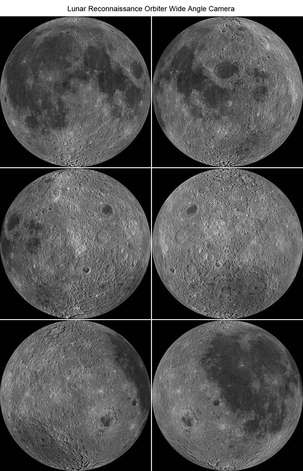
As the mission progresses, and our knowledge of the lunar photometric function increases, improved and new mosaics will be released! Work your way around the Moon with these six orthographic projections constructed from WAC mosaics. (The nearside view linked below is different from that released February 21.)


Six orthographic views of the Moon created from the new Lunar Reconnaissance Orbiter Camera WAC global mosaic; upper left to lower right the central longitude is 0°, 60°, 120°, 180°, 240°, 300° East longitude. View the full preview image above HERE [NASA/GSFC/ Arizona State University].

WAC mosaic orthographic view centered at 0° longitude
WAC mosaic orthographic view centered at 60° longitude
WAC mosaic orthographic view centered at 120° longitude
WAC mosaic orthographic view centered at 180° longitude
WAC mosaic orthographic view centered at 240° longitude
WAC mosaic orthographic view centered at 300° longitude

Saturday, October 16, 2010

Sinus Iridum - Next Destination?


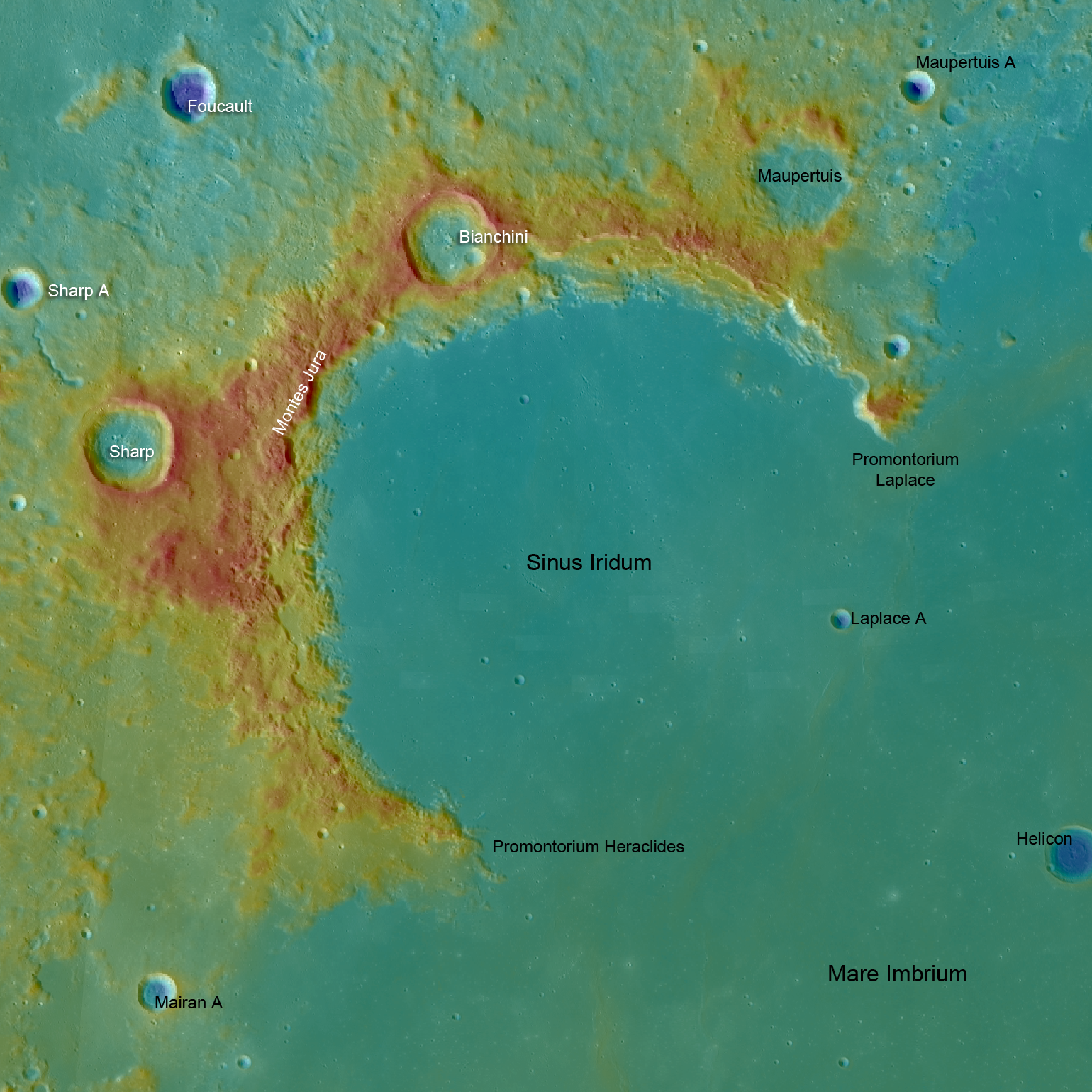
LROC Wide Angle Camera (WAC) topography of Sinus Iridum. Blue shows the lowest areas and red the highest. From Promontorium Heraclides to Promontorium Laplace is 235 kilometers across [NASA/GSFC/Arizona State University].

Mark Robinson
Principal Investigator
Lunar Reconnaissance Orbiter Camera
Arizona State University


Wow - five spacecraft launched to the Moon in three years! The latest is China's second lunar orbiter, Chang'e 2, which was launched 1 October 2010 and arrived at the Moon on 6 October. Chang'e 2 carries a higher resolution camera than Chang'e 1 that may help Chinese scientists scout out the proposed landing site for their upcoming lander/rover, Chang'e 3. Currently the Chinese lander is slated to land in Sinus Iridum (Bay of Rainbows) sometime before 2013. Why Sinus Iridum? The WAC topographic map shows the area to be very flat and nearly featureless. However as the LROC Narrow Angle Camera (NAC) keeps showing us, there are no featureless spots on the Moon - everywhere on the Moon is fascinating!


Boulders resting on the top of a wrinkle ridge in the middle of Sinus Iridum. Where did they come from? (LROC Narrow Angle Camera observation M124749832R) [NASA/GSFC/Arizona State University].

Sinus Iridum is a mare-filled impact crater that superposes the Imbrium basin. It is far from any Apollo landing sites, with the closest (Apollo 15) being more than 1000 km distant. Scientists would love to have a look at the chemistry of these basalts - how much do they differ from the Apollo 15 basalts which are from the other side of Imbrium? Wrinkle ridges cross the mare, and in places families of boulders are perched on the ridges. Are the boulders weathering out of the ridge? Many small irregular shaped craters dots Sinus Iridum, how were they formed? The LROC team will post selected NACs over the coming weeks, you can join the effort to explore this future landing site now!

Explore the whole of Sinus Iridum with a WAC BW mosaic!

The topographic color was produced as a by-product of stereo analysis of the WAC global dataset. Producing the global Digital Elevation Model (DEM) is a big job being led by LROC team members at the German Aerospace Center (DLR; English version) in Berlin. This winter a global 100 meter DEM will be released.

Monday, September 6, 2010

Lunar superlatives from LROC WAC


The 'Rooftop of the Moon' appears to be on the wide, flat northwest rim of 43 km-wide Engel'gard, the largest crater in this monochrome sample from the LROC Wide Angle Camera. The actual spot (5.44°N, 201.36°E) is not immediately distinct, as are Everest or Denali, for example. A future traveler standing there, 10.75 km above the global mean elevation might notice little beyond a close horizon. A brief 'bunny hop' may be necessary to get to an overlook, to see breathtaking views of astounding depths and distances. LROC WAC observation M103209735ME, field of view roughly 100 km; LRO orbit 379, July 26, 2009; alt. 112.88 km, res. 178.3 meters, phase angle 66.22° [NASA/GSFC/Arizona State University].


Barely 2400 km from the Moon's highest point is it's lowest point, invisible above, inside the shadows of the 12 km crater at middle-left, within the wide interior of 143 km-wide Antoniadi, not far from the center of 4 billion year old South Pole-Aitken basin. From Kaguya the smaller crater's interior (70.43°S, 187.42°E) was measured to a depth of 9.06 km below global mean (19.85 kilometers below the high point at Engle'hardt and 2 km more than the range gauged as recently as 2005). This image was processed using LROC WAC Previewer (v.1.2) from LROC WAC observation M103254154ME; field of view approximately 150 km; LRO orbit 385, July 26, 2009; alt. 42.68 km, res. 66.03 meters, phase angle 82.5° [NASA/GSFC/Arizona State University].


The bright, highest of the Moon's highlands as seen from Kaguya as the orbiter sailed under a late morning Sun. [JAXA/NHK/SELENE].


Also from Kaguya, the Moon's lowest place (70.43°S, 187.42°E) is briefly seen at the bottom of the bowl-shaped crater in wider Antoniadi. All the scenery in this late mission Terrain Camera image averages a few kilometers lower in lunar elevation than anything we can see of the Moon's near side from Earth. [JAXA/SELENE].

Wednesday, August 26, 2009

First LROC Stereo results from LRO


Synthetic perspective view looking south from the Apollo 16 landing area, topography is rendered naturally (no vertical exaggeration) and Perspective view, LROC image and Digital Elevation Model [NASA/GSFC/Ohio State University via LROC ASU] Though originally believed to be a geological disappointment, because the region did not yield evidence of volcanism in the manner hoped, the landing area of Apollo 16 is high on the list of the fifty most important future landing sites. Analysis of magnetic field data collected by Lunar Prospector showed the high albedo on the Descartes Formation to be coincident with a Lunar Magnetic Anomaly, topography there shows unique characteristics and the geology of the area has become a standard reference for missions like Japan's Kaguya.