Tuesday, March 19, 2013

Graves of the GRAIL twins

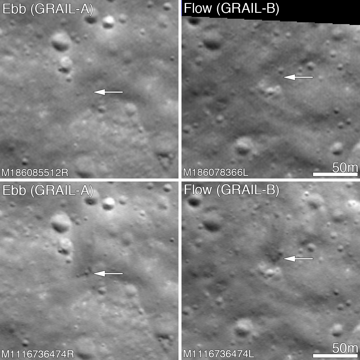
Before and after the GRAIL twins impacts on the Moon December 17, 2012. The LROC Narrow Angle Camera (NAC) directors were able to resolve the impact sites on February 28, 2013, revealing both to be about 5 meters in diameter. Upper panels show the area before the impact; lower panels after the impact. Arrows point to crater locations. LROC NAC observations M186085512R, M186078336L, M1116736474R and M1116736474L. Full size Featured Image HERE  [NASA/GSFC/Arizona State University].
Jeffrey Plescia
LROC News System

The Gravity Recovery and Interior Laboratory (GRAIL) mission ended on 17 December 2012 at 14:28 PST (-8 hrs. relative to Universal Time) when the two spacecraft GRAIL A (Ebb) and GRAIL B (Flow) impacted the Moon.

Both impact sites lie on the southern slope of an unnamed massif (mountain) that lies south of the crater Mouchez and northeast of the crater Philolaus.

The massif stands as much as 2500 m above the surrounding plains. The impact sites are at an elevation of about 750 and 1040 meter, respectively, about 460-750 m below the summit.

Artist conception of the orbital track of the two spacecraft just before impact. Both spacecraft were tracking north as their altitude continuously decreased until they impacted the south side of the massif [NASA/JPL].
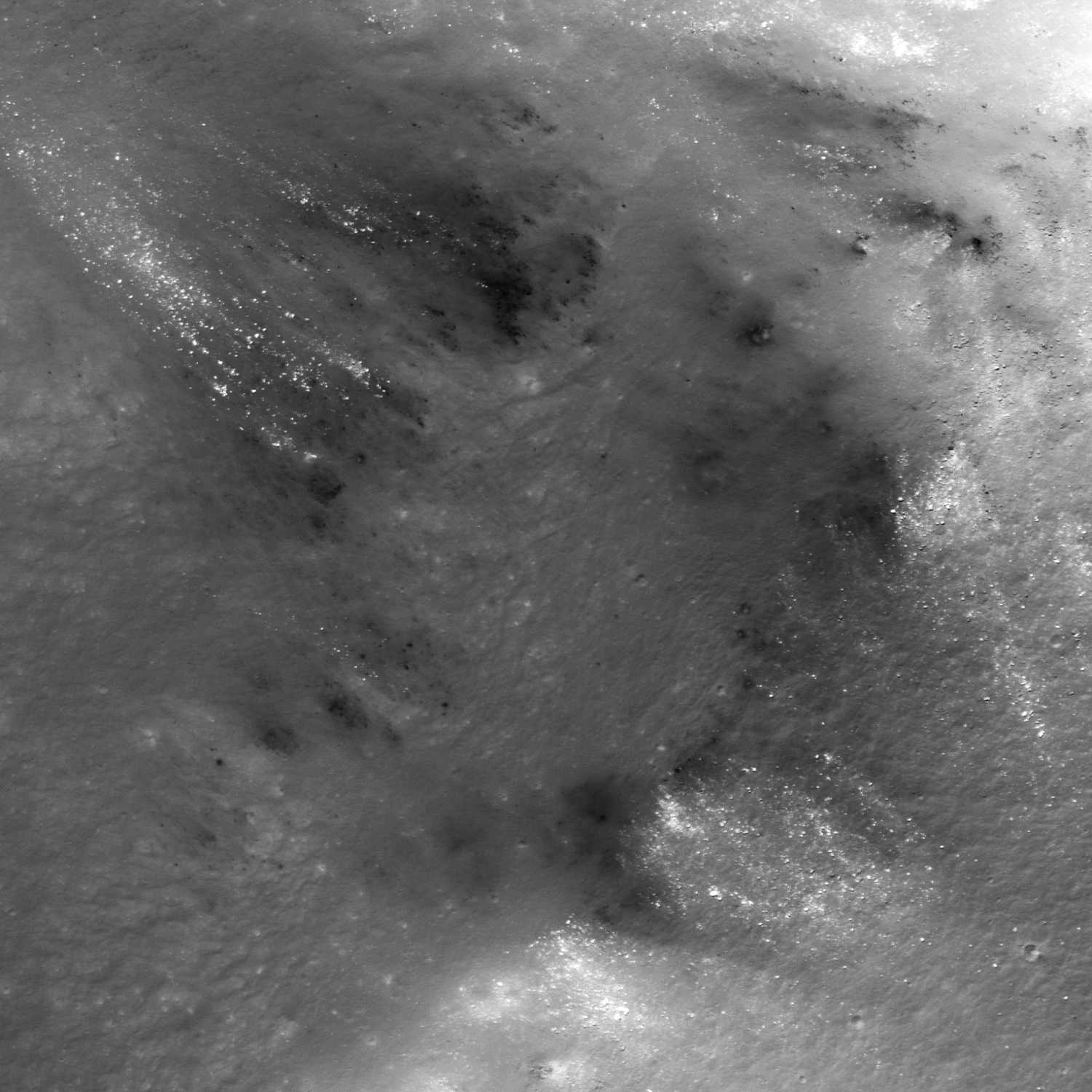
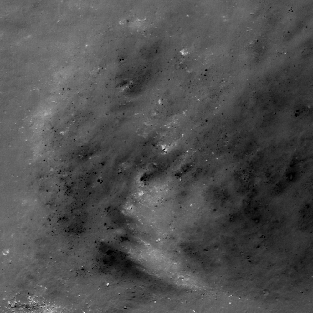
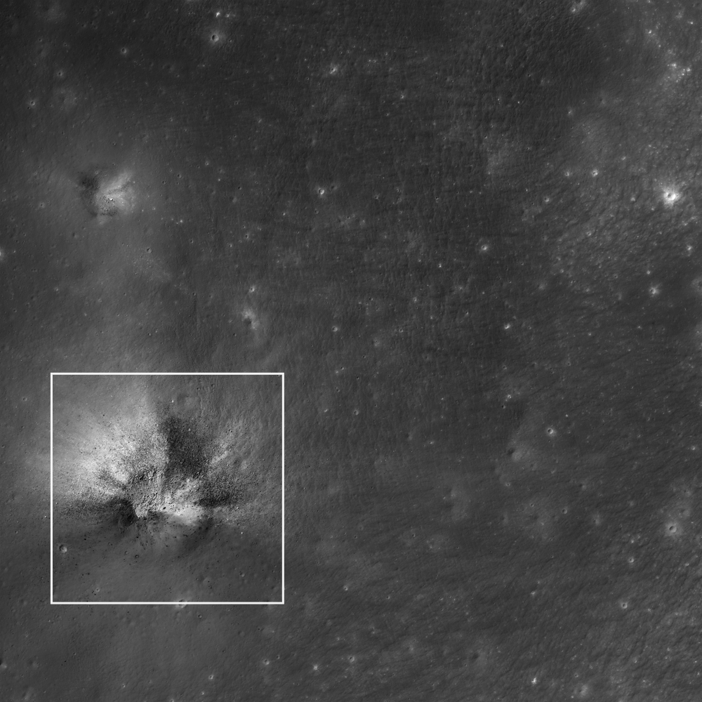
The two GRAIL spacecraft were relatively small - cubes about the size of a washing machine with a mass of about 200 kg (441 lbs) at the time of impact. When they arrived at the Moon their mass was closer to 278 kg (619 lbs), but about 78 kg (172 lbs) of that was fuel consumed during lunar operations. Both spacecraft impacted at very low angles (~2° to the horizontal) at about 1600 m/s (faster than a speeding bullet) into a fairly steep slope! LROC images reveal that both spacecraft formed craters about 5 m (15 ft) in diameter. Surprisingly, the ejecta around both craters is dark and irregularly distributed around the crater; there is little ejecta to the south - the direction from which the spacecraft were traveling.

GRAIL A site seen before and after the impact event. Crater center is located at 75.609°N, 333.407°E [NASA/GSFC/Arizona State University].
Typically ejecta from craters has a higher reflectance than the target material (think of the rays of Tycho). This normal contrast is due to the excavation of fresh (or immature) soil from beneath a more mature, weathered layer. As the lunar regolith is exposed to the vacuum of space, it suffers exposure to cosmic radiation, solar wind bombardment, and micrometeorite impacts. Slowly over time, these processes tend to darken the soil. Thus, if you dig down beneath the surface you will find higher reflectance soil.

GRAIL B site seen before and after impact event. Crater center is located at 75.651°N, 333.168°E [NASA/GSFC/Arizona State University].
So why do both GRAIL craters exhibit low reflectance rays? Perhaps we are seeing carbon from the spacecraft. The structure was made of a cyanate ester composite (carbon rich) and other materials also had carbon as primary compounds. Additionally, there was about 0.5 kg (1.1 lbs) of fuel remaining in each spacecraft. Due to the energy of impact, the carbon from these varied sources may have been released and mixed with and coated the ejecta. It takes only a very small amount of carbon to darken a material, recall in art class when you put just a few drops of black paint into a lighter color and it went all muddy. But right now we do not know for sure the cause of this interesting anomaly!

LRO Wide Angle Camera (WAC) image of the GRAIL impact area on the south side of the unnamed massif. LRO WAC M120020350 [NASA/GSFC/ASU].
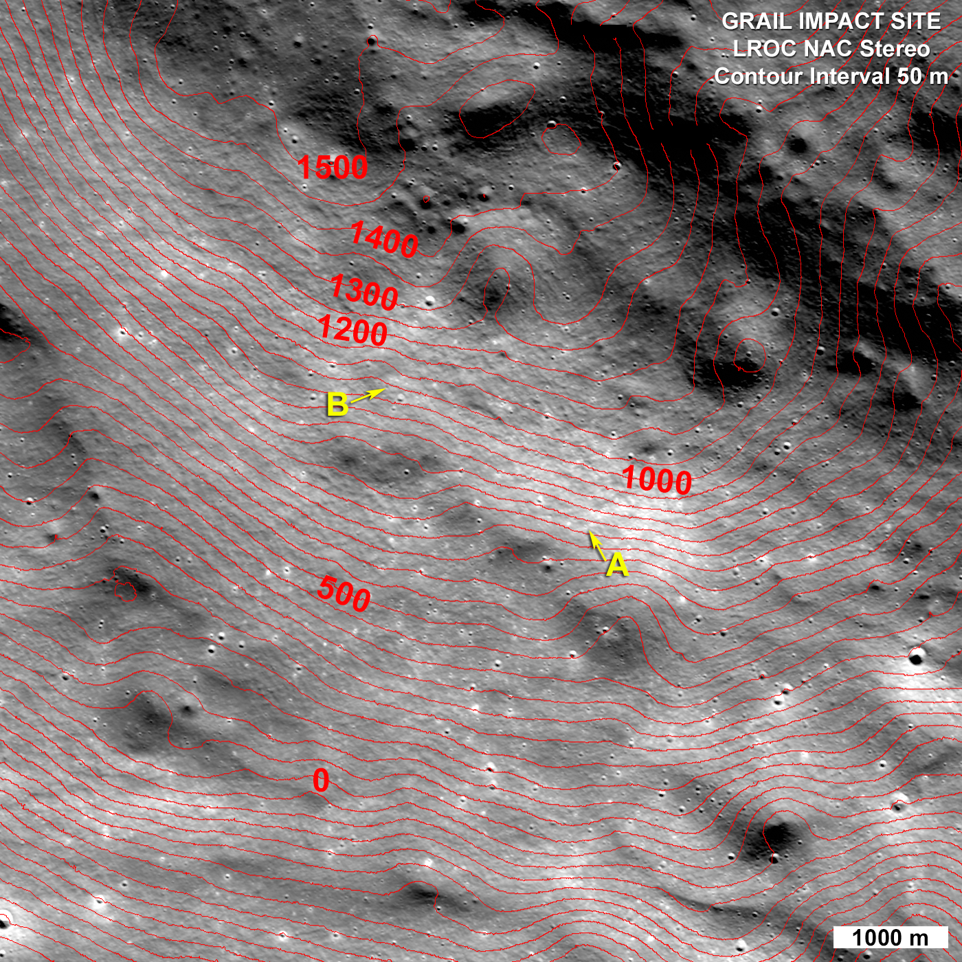
On 28 February 2013 the LROC obtained a stereo pair for the impact area and from these images the LROC team produced a controlled preliminary topographic map. From the stereo model latitude, longitude and elevation were derived for each impact crater: GRAIL A 75.609°N, 333.407°E, 750 meters and for GRAIL B 75.651°N, 333.168°E, 1040 meters. The local slope of the mountain at the point of impact was 23° for GRAIL A and 19° for GRAIL B. As knowledge of the spacecraft position is refined the LROC team will update these coordinates. The two impact craters are about 2210 m apart; GRAIL B impacted about 20 seconds after GRAIL A at a site to the northwest of GRAIL A.

LROC NAC stereo derived topographic map of the GRAIL Impact area, map is 8400 meters wide, north is up [NASA/GSFC/Arizona State University].
Find the GRAIL impact craters in the full NAC image, HERE.

Related Posts:
Parting shots from Ebb MoonKAM prior to impact
Ebb and Flow Finale
Rocket Impacts Recorded by the Apollo Seismic Network
Apollo 14 S-IVB Impact Crater
Mountains of the Moon
LROC Coordinates of Robotic Spacecraft
Ejecta Sweeps the Surface

Monday, March 18, 2013

Golden Spike and LPI schedule 2013 conference

Notional view of NASA's recently-abandoned Altair lunar lander, on a pad in the Moon's high northern latitudes formed from sintered regolith. Golden Spike Company announced in January Altair's designer Northrup Grumman to initiate design work on a manned lunar lander to return to the Moon by 2020.
The Golden Spike Company of Boulder, Colorado has announced an international workshop next October "to explore the kinds of landing sites, experiments, and geological traverses their astronauts should undertake on the Moon starting in 2020."

The two-day seminar will be held at the Lunar and Planetary Science Institute (LPI) in Houston, October 3-4, 2013.  

The program committee includes Alan Stern, Golden Spike CEO and President, Steve Mackwell of the Lunar and Planetary Institute, Clive Neal of Notre Dame, William McKinnon of Washington University, Amand Mahesh of Open University, Dr. Daniel Durda of the Southwest Research Institute (SwRI) and James Carpenter of the European Space Agency.

“We’re excited to announce this workshop, which will seek input from lunar researchers from across the world regarding scientific priorities for Golden Spike expeditions, Stern said. "We also expect this workshop to multiply interest in our missions from science and space agencies across the globe.”

“It is great to be part of the beginning of a new age of space exploration where commercial entities step up as key enablers of manned exploration of the solar system, and it is so appropriate this first meeting will be held at the Lunar and Planetary Science Institute, with its roots in the Apollo era,” Mackwell added.

The workshop will consist of plenary and a poster sessions organized around topical themes, invited presentations, and discussion panels. Stern and Golden Spike’s board chair Gerry Griffin, former director of the Johnson Space Center in Houston, will offer a public presentation about Golden Spike, Thursday evening, October 3.

More information about this workshop, including an opportunity to provide an expression of interest in attending and potentially speaking, can be found HERE.

Related Posts:
Golden Spike taps Northrup Grumman to design manned lunar lander
(Ben Evans, AmericaSpace, January 13, 2013)
Turning science fiction to science fact (Jeff Foust, The Space Review, December 11, 2012)

Sunday, March 17, 2013

Conjunction of Jupiter and Moon at sunset

Mirror Image - conjunction of Jupiter with its Galilean Moons and Earth's Moon, in the east ahead of sunrise, July 2012. From a widely circulated image by astrophotographer Cristian Fattinnanzi. After sunset on St. Patrick's Day 2013, observers will have an opportunity to view a kind of mirror image in the west, after sunset. More fortunate or better situated observers may also view auroral activity following an Earth-directed Coronal Mass Ejection that impacted Earth's magnetic field at 0600 UT, March 17. A map of conjunction has been uploaded by SpaceWeather.com.

Saturday, March 16, 2013

First laser comm system ready for launch on LADEE

Lunar Laser Communication Demonstration (LLCD) components integrated onto the Lunar Atmosphere and Dust Environment Explorer (LADEE) spacecraft [NASA].
Dewayne Washington
Goddard Space Flight Center

A new NASA-developed, laser-based space communication system will enable higher rates of satellite communications similar in capability to high-speed fiber optic networks on Earth.

The space terminal for the Lunar Laser Communication Demonstration (LLCD), NASA's first high-data-rate laser communication system, was recently integrated onto the Lunar Atmosphere and Dust Environment Explorer (LADEE) spacecraft at NASA's Ames Research Center, Moffett Field, California. LLCD will demonstrate laser communications from lunar orbit to Earth at six times the rate of the best modern-day advanced radio communication systems.

"The successful testing and integration of LLCD to LADEE is a major accomplishment," said Donald Cornwell, LLCD mission manager at NASA's Goddard Space Flight Center in Greenbelt, Maryland. "It demonstrates that this new technology is robust and ready for space. This is the first time NASA has had such a communication system pass all its tests and be certified flight ready."

The LLCD mission will use a highly reliable infrared laser, similar to those used to bring high-speed data over fiber optic cables into our workplaces and homes. Data, sent in the form of hundreds of millions of short pulses of light every second, will be sent by the LADEE spacecraft to any one of three ground telescopes in New Mexico, California and Spain.

S-band communications aboard the LADEE spacecraft would take 639 hours to download an average-length HD movie. Using LLCD technology that time would be reduced to less than eight minutes.

The real challenge of LLCD will be to point its very narrow laser beam accurately to ground stations across a distance of approximately 238,900 miles while moving. Failure to do so would cause a dropped signal or loss of communication.

"This pointing challenge is the equivalent of a golfer hitting a ‘hole-in-one' from a distance of almost five miles," said Cornwell. "Developers at the Massachusetts Institute of Technology's (MIT) Lincoln Laboratory have designed a sophisticated system to cancel out the slightest spacecraft vibrations. This is in addition to dealing with other challenges of pointing and tracking the system from such a distance. We are excited about these advancements."

The LLCD mission will also serve as a pathfinder for the 2017 launch of NASA's Laser Communication Relay Demonstration (LCRD). That mission will demonstrate the long-term viability of laser communication from a geostationary relay satellite to Earth. In a geostationary orbit the spacecraft orbits at the same speed as Earth, which allows it to maintain the same position in the sky.

Engineers believe that future space missions will be able to use laser communication technology with its low mass and power requirements, to provide increased data quantity for real-time communication and 3-D high-definition video. For example, using S-band communications aboard the LADEE spacecraft would take 639 hours to download an average-length HD movie. Using LLCD technology that time would be reduced to less than eight minutes.

Prior to shipment from MIT, the LLCD spaceflight hardware was subjected to a rigorous set of flight test simulations such as the strong vibrations expected from a Minotaur V rocket, the launch vehicle for the LADEE mission. The LLCD hardware also had to withstand simulated extreme temperatures and other conditions it will experience within the harsh environment of space. Throughout this stringent battery of tests, LLCD maintained its critical alignment and stable pointing accuracy.

Flight and ground station hardware for LLCD was designed and built at Lincoln Laboratory in Lexington, Mass. NASA's Jet Propulsion Laboratory in Pasadena, Calif., and the European Space Agency are developing the ground stations in California and Spain, respectively.

"This is an exciting time for space communications," said Cornwell. "We are about to make a leap in communications ability that is unmatched in NASA's history."

The LLCD mission management team resides at Goddard under the sponsorship of the Space Communications and Navigation (SCaN) Program at NASA Headquarters in Washington. The LADEE mission is managed by Ames under the sponsorship of NASA's Planetary Science Division within the Science Mission Directorate at NASA Headquarters.

NASA's Science Mission Directorate in Washington funds LADEE, a cooperative effort led by Ames, which is responsible for managing the mission, building the spacecraft and performing mission operations. In addition to managing the LLCD payload, Goddard is responsible for managing the science instruments and the science operations center. NASA Wallops Flight Facility has the responsibility for launch vehicle integration, launch services and launch range operations. NASA's Marshall Space Flight Center, Huntsville, Alabama, manages LADEE within the Lunar Quest Program Office.

The LADEE mission, on which LLCD is a hosted payload, is scheduled to launch in August.

Related Posts:
LADEE project manager update (February 6, 2013)
The Mona Lisa test for LADEE communications (January 21, 2013)
Expectations for the LADEE LDEX (March 23, 2012)
LADEE architecture and mission design (July 6, 2010)
NASA applies low cost lessons to LADEE (January 18, 2010)
LADEE launch by Orbital from Wallops Island (April 14, 2009)

Thursday, March 14, 2013

Low reflectance deposits on Lassell Massif

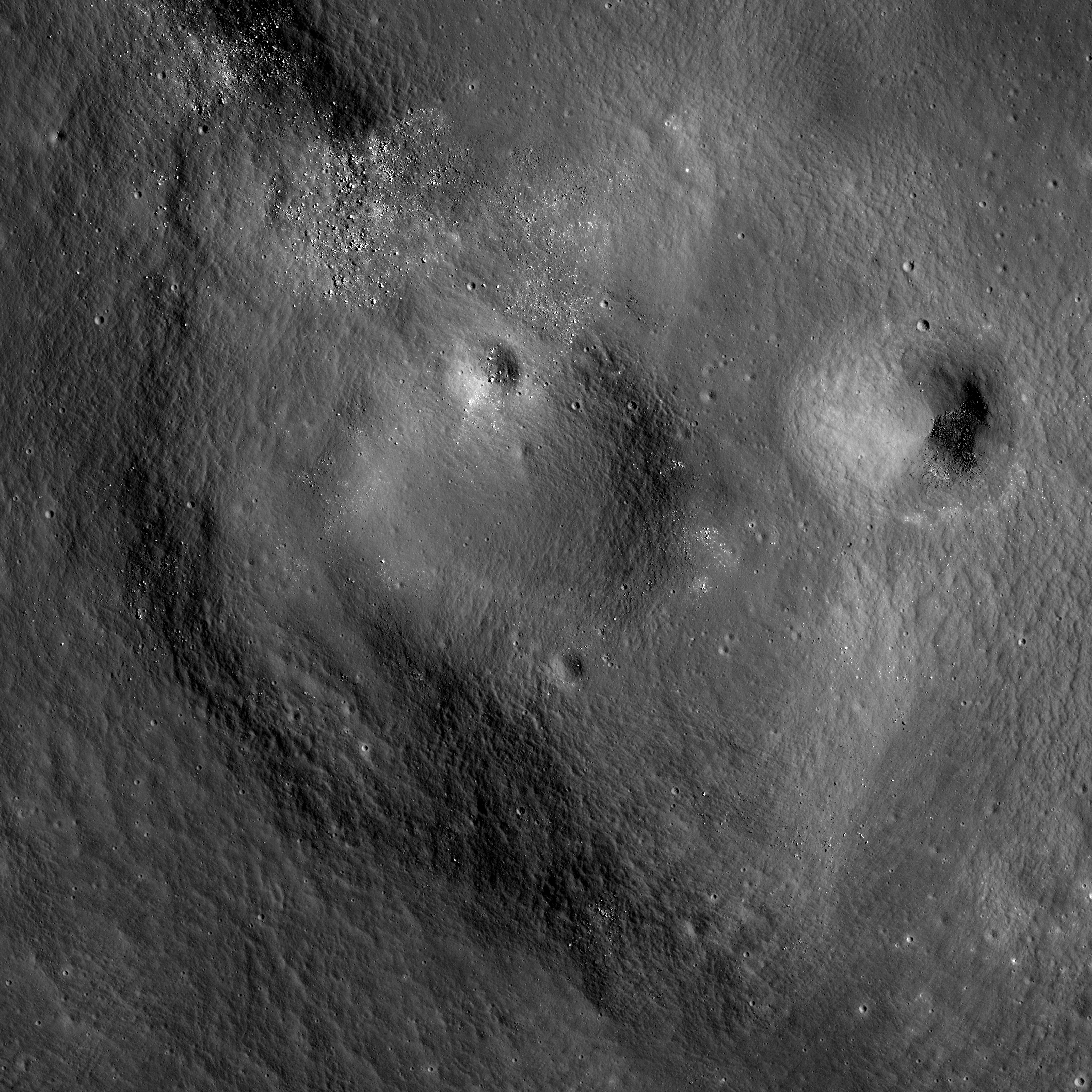
Low reflectance deposits are seen along the margins of the double 'vent-like' depressions Lassell G and Lassell K (14.918°S; 351.065°E) in Mare Nubium. LROC Narrow Angle Camera (NAC) observation M1116585481R, LRO orbit 16774, February 27, 2013; Sun is overhead, north is up, field of view roughly 1.8 km across at 0.88 meters resolution [NASA/GSFC/Arizona State University].
James Ashley
LROC News System

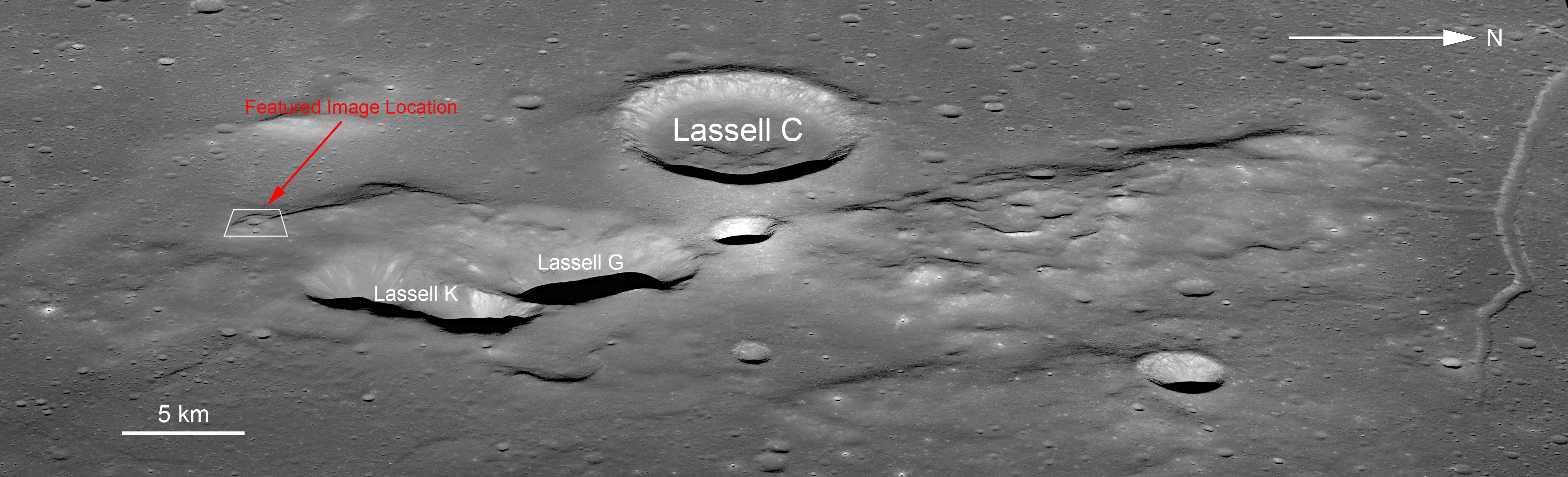
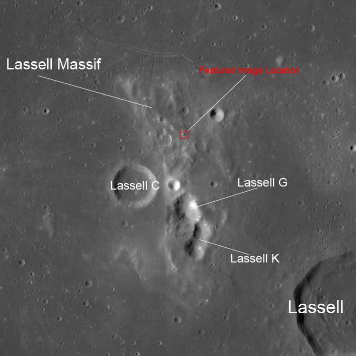
Today's Featured Image follows up on the two previous posts with another look at the Lassell Massif region of Mare Nubium. These prominent low reflectance deposits line the rims of the Lassell G and Lassell K pit features (see context image below). Their occurrence along the pit rims suggest a dark layer may be present just beneath the regolith surface, whose exposure has been encouraged by mass wasting in the pit walls. What caused such steep walled pits, and what are these low reflectance materials?

Our geologic train of thought continues from yesterday's post. We were discussing the geochemical differences between iron-rich, silica-poor (basaltic) and iron-poor, silica-rich (rhyolitic) magmas in the inner Solar System. But why should this matter, and what does it have to do with our images this week? The short answer is that basaltic lavas (and basaltic impact melts) have low viscosity, where rhyolitic lavas have relatively high viscosity. Basaltic extrusions filled mare basins like lakes, cascaded over fault blocks like waterfalls, and flowed like molten rivers on the Moon. On Earth and Mars they form flood basalt deposits and low-topography shield volcanoes. By contrast, rhyolitic lavas can be visualized as having a pasty or sticky consistency. They form steeper slopes, flow more sluggishly, develop high constructs, and can erupt explosively.

Mt. St. Helens and other Cascade volcanoes are good examples for Earth.

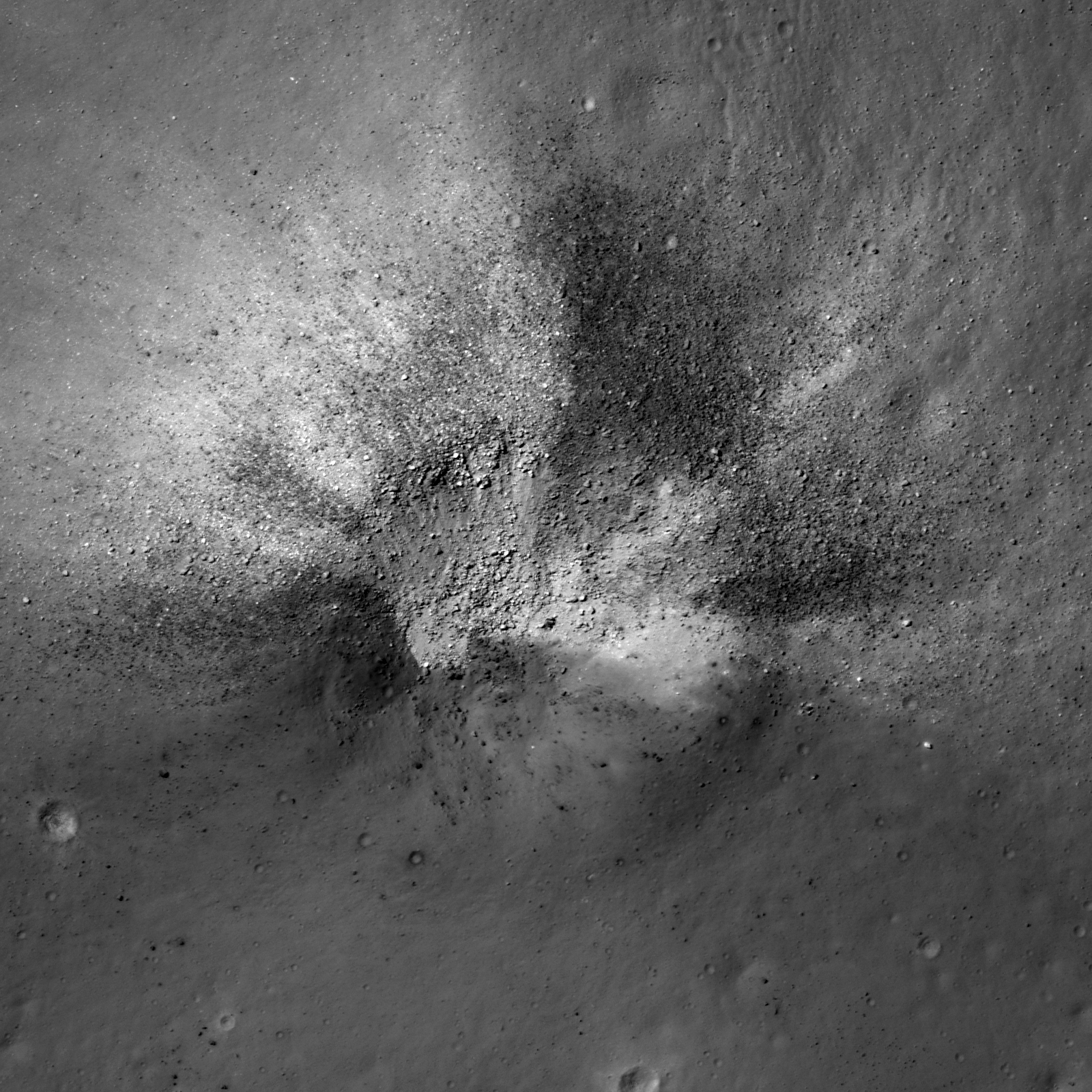
Another portion of NAC frame M1116585481R shows fragmented dark deposits [NASA/GSFC/Arizona State University].
A story of complex volcanism is emerging for the Lassell Massif region. The dark deposits may be pyroclastic in origin, and may have come from the massif source magmas themselves, or from adjacent volcanic fountaining (the floor of Lassell crater out of frame to the lower right of the context image is suspected to contain pyroclastic deposits). Based on LRO Diviner data the massif itself is silica-rich, which accounts for its topography, and suggests that Lassell G and Lassell K may be collapse calderas. They have very steep slopes and V-shaped profiles, in contrast to impact features.

LROC Wide Angle Camera (WAC) mosaic context image, outlining the areas spotlighted in this and two other LROC Featured Images, released the week of March 11, 2013 . The light yellow square encloses the area in today's Featured Image [NASA/GSFC/Arizona State University].
Another look, from another angle, at the south Lassell complex, allowing some perspective of the topography - steep drops on either side of a shared wall - of the area highlighted in the Featured Image - from the newly-released LROC NAC oblique mosaic M1108311369LR, linked HERE [NASA/GSFC/Arizona State University].
Explore the full NAC frame HERE. Other examples of silica-rich, so-called 'intrusive' lunar volcanism may include the Gruithuisen Domes, features in Compton-Belkovich and the Hortensius Domes.

Wednesday, March 13, 2013

"That sounds familiar"

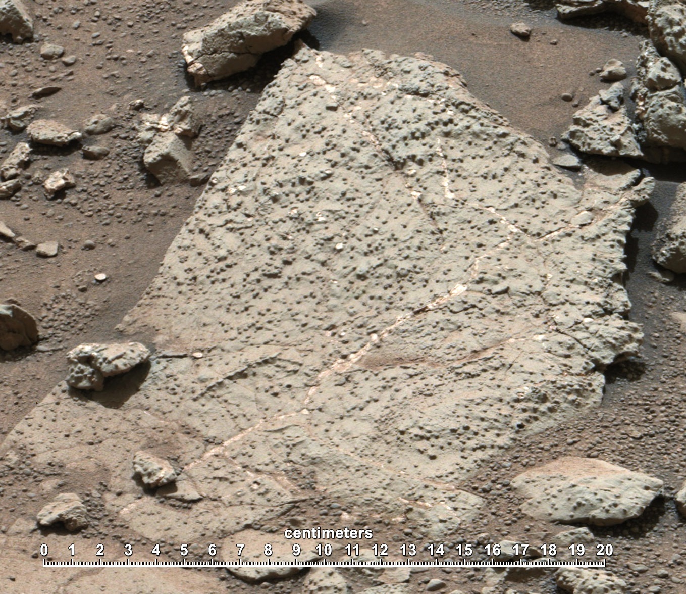
Sedimentary rock on Mars as viewed and analyzed by the Curiosity rover [NASA].
Paul D. Spudis
The Once & Future Moon
Smithsonian Air & Space

The news of the day is abuzz with the new and astounding discoveries from the Curiosity rover that Mars once had an environment conducive to life.  Once it was warmer, wetter, more hospitable.  Water flowed over its surface.  The chemicals necessary for life’s emergence and development are present on Mars, suggesting that life may have arisen there in the distant past.  So why do I have this sense of déjà vu?  Perhaps because this new “result” gets trumpeted anew every few years.

The fixation on the possibility of martian life has been a constant throughout the history of the space program, starting before the first planetary mission to Mars in 1965 (Mariner 4) and then waxing and waning in likelihood every few years.  Mariner 4 showed us a moon-like Mars, with a rough, cratered surface and thin cold atmosphere.  The stock for martian life fell accordingly.  

A few years later, the twin probes Mariners 6 and 7 flew by Mars, again returning pictures of a cratered surface, but with hints of the presence of unusual terrain, possibly the result of subsurface ice.  The stock of the life story rose slightly, but the barren cold desert of the martian surface was hardly a Garden of Eden.

A big breakthrough came with the flight of Mariner 9 in 1971.  To the astonishment of most planetary scientists, it revealed a world of giant volcanoes, canyons much larger than the Grand Canyon on Earth, and amazingly, channels that looked as though they were carved by running water.  The idea of life on Mars – at least in the distant past – gained credence and served as a springboard for the Viking missions of 1976, America’s bicentennial year.  These two missions consisted of both a lander and an orbiter and were specifically designed to test the surface of Mars for the possibility of life.  Both landers returned results that were immediately interpreted as negative (although there was some dissent); the surface materials of Mars had a very reactive chemistry, but no organic material was found in the soil, even at concentration levels measured in parts-per-billion.  Thus, we had the conundrum of abundant landform evidence for an early, warm and wet climate yet chemical evidence for an almost sterilizing environment at present.  If Mars had life, it must have been present only in the distant past.  The results from Viking were considered so definitive that no mission was sent to Mars for over 20 years.

What precipitated the new flurry of interest in Mars about twenty years ago was the finding that, astonishingly enough, we have samples in our possession from Mars in the form of meteorites, the so-called “SNC meteorites” (the initials of Shergotty, Nakhla, and Chassigny, the first three meteorites recognized to be of martian origin).  It had been thought that the preservation of rocks intact during ejection from the planet at escape velocities and greater was not possible, but in this case, observations trumped theory.  Even more amazing, it was claimed that in one of these putative martian rocks, small features within it were actually fossils of ancient bacteria.  Although highly controversial then (and now), this finding was given widespread publicity (including even a Rose Garden Presidential statement) and the agency used this discovery to sell a program to send a series of probes to Mars at every two-year opportunity for the next decade.

This fleet of orbiters and landers returned an abundance of new, high-quality data on the martian surface, its composition, the locations of water and its environment.  Each mission confirmed that water had once been present on Mars.  Each mission confirmed that at present, the surface was not conducive to life.  Each lander went to a site that was thought to have been more promising for the development of life than the ones that preceded it.  As the years rolled on, each “new discovery” of the former presence of water and favorable environmental conditions on Mars became something of a joke among my colleagues in the planetary science business – how many times can you claim the discovery of something already known?

Lest you think that I am simply expressing my lunar parochialism, I note that this same media phenomenon occurs in regard to the existence of water ice at the poles of the Moon.  The theoretical possibility of ice on the Moon had been known for many years.  We first found direct evidence for it in 1996 with an improvised radio experiment on the Clementine mission.  Subsequent studies from Earth and a variety of other space missions caused the stock for lunar polar water to rise and fall, depending on who issued the latest press release for their published work.  Finally, the collision of the LCROSS impactor in 2010 removed all doubt – there was and is ice there, at least at the south pole and in quantities greater than could be reasonably expected to have resulted simply from solar wind deposition.  Yet each new finding was announced as a new “discovery” in the press.  So this media frenzy is not simply related to Mars mania or even to the over-preoccupation with finding life elsewhere.

The basic fact is that most in the news business do not understand (or at least, do not fully appreciate) the incremental, cumulative nature of modern science.  It is seldom indeed when a single experiment or observation causes a scientific revolution.  Moreover, it is equally seldom that a breakthough comes from one person or even one research team.  Science is a complex, interdisciplinary effort.  It makes progress, but slowly and in a manner that includes both leaps forward and (sometimes) backward.  Only over long periods of time (decades and greater) is it apparent what the key observation or measurement is and how it fits into a pattern of understanding.  Each new mission result adds knowledge, sometimes in great leaps and sometimes in increments so tiny that one can question whether anything new is being learned at all.  But even a repeated observation has value in science – in fact, if an observation is not repeatable, it is not a valid scientific observation.

The new inferences from Curiosity suggest a more benign and hospitable environment for life, but few working Mars investigators doubted that such existed in the past.  Even if it did not, we have found in the past few decades that even extreme environments on the Earth can support certain types of microbial life.  So the new results broaden and deepen our understanding of martian surface properties and processes, they do not revolutionize them.  That’s just how science normally works.  If some scientists tend to oversell their results, well, they’re only human.

Originally published at his Smithsonian Air & Space Magazine blog "The Once and Future Moon," Dr. Spudis is a senior staff scientist at the Lunar and Planetary Institute. The opinions expressed are those of the author and are better informed than average.

LROC 13th Release to the Planetary Data System

Quick assessment of the LROC Narrow Angle Camera (NAC) frames covering just the near side of the Moon captured between mid-September and mid-December 2012, over just 90 days, during the on-going science phase of the LRO mission. These images are among those released to the Planetary Data System, March 13, 2013. LROC PDS Interface WMS map [NASA/GSFC/Arizona State University].
Ernest Bowman-Cisneros
LROC News System - Announcements

The 13th LROC Planetary Data System release includes images acquired between 2012-09-16 to 2012-12-15. This release contains 75,274 EDR images totaling 8.09 TB and 75,274 CDR images totaling 16.68 TB. An additional 9 LROC NAC Digital Terrain Models (DTM) and 6 NAC Region of Interest (ROI) products were also added to the LROC RDR Dataset.

To date, the LROC Team has delivered 970,789 LROC images and over 8,743 derived (RDR) data products to the NASA Planetary Data System. The complete LROC PDS archive can be accessed via the URL http://lroc.sese.asu.edu/data or one can search for specific images or mosaics using the LROC WMS browser. Also be sure and try out Quickmap!

Cinder Cone, Impact Crater, or Something Else?

A circular feature piques curiosity and encourages speculation (15.228°S; 350.923°E). LROC Narrow Angle Camera (NAC) frame M160010100R, LRO orbit 8714, May 14, 2011; illumination is from the east (north is up), angle of incidence 51.22° Field of view roughly 1.8 km wide, resolution 48 cm per pixel from 40.49 km [NASA/GSFC/Arizona State University].
James Ashley
LROC News System

Continuing our discussion of the Lassell Massif region of Mare Nubium (see yesterday's Featured Image post HERE), we migrate to the southern end of the massif proper, where we find a distinctive circular feature. At first glance this appears to be an ancient, degraded impact crater -- and this could very well be the correct explanation. It also, however, bears a morphologic similarity to cinder cones seen elsewhere on the Moon (Lacus Mortis, for example). This degraded circular feature has inner rim slopes of ~5°, outer flank slopes of 4-10°, and a height of ~60m, similar to the dimensional proportions of a cinder cone. Cinder cones are another example of pyroclastic volcanism, when eruptions are energetic enough to loft material above the surface, where it cools and descends to collect in piles on the ground. 

LROC Wide Angle Camera (WAC) mosaic context view of the Lassell formation. The square at bottom encompasses the field of view covered by the LROC Featured Image released March 13, 2013, as the square above references the previous day's LROC release. [NASA/GSFC/Arizona State University].
To understand the context for this feature, and indeed the Lassill Massif itself, we must first review a brief introduction to geochemical evolution and planetary volcanism in general.

According to current models, when a star forms within an interstellar molecular cloud (together with its orbiting planets), the individual objects within this new solar system have a similar starting composition chemically. This is why CI carbonaceous chondrite meteorites (among the most primitive materials in the solar system) have essentially the same composition as our Sun (minus the hydrogen and helium, of course). When enough internal heat builds up inside a planet, moon, or asteroid to partially melt this material, the result is a magma rich in iron and magnesium, and the rock that forms after cooling is a dark-colored basalt.

Thus basalt is the easiest igneous (from a melt) rock a planetary body can make. We find basalt on Mercury, Venus, Earth, Mars, the asteroid Vesta, and the Earth's Moon, and it is no surprise at all. Basalt is what makes up the dark features on the Moon. Now if basalt is partially melted, an even more geochemically "evolved" magma is produced. The process can continue to result in ever-more silica-rich, iron-poor rock products. Eventually granitic / rhyolitic magmas are produced. This is easy to do on the Earth where plate tectonics provides these mechanisms. Its anomalous on a body like our Moon, where plate tectonics does not take place.

Though surrounded by the basalts of Mare Nubium, infrared data from the Lunar Reconnaissance Orbiter Diviner instrument confirm a silica-rich nature to the Lassell Massif construct. For the reasons outlined above, this is somewhat anomalous to our current understanding for how lunar volcanism works.

A Digital Elevation Model of the feature and associated topography. Color scale indicates approximately 160 meters of relief from lowest (yellow) to highest (magenta) elevation. Black arrows show lobate margins of suspect high-viscosity flows. Area covered is approximately 7 km wide [NASA/GSFC/Arizona State University].
The Digital Elevation Model for the Featured Image region provides topography as a color scale where yellow is low elevation and red tones are high elevation. The black arrows highlight what appear to be lobate flow structures that superpose the circular feature. These lobate materials present a silica-rich spectrum, while the underlying half of the circular feature do not. Whatever this landform is -- cinder cone, impact crater, or perhaps simply a geologically insignificant depression coincident with a moderately round lump of debris -- it was deposited before the silica-rich deposits were emplaced on top. Once again we see that our Moon is more complex geologically than previously thought!

The oblique image below provides the type of view that Command Module Pilot Ken Mattingly must have had during his Apollo 16 survey of the area in 1972.

Thumbnail of a greatly reduced oblique context image of the Lassell Massif region (see larger version HERE), facing west; LROC NAC mosaic M1108311369LR,  [NASA/GSFC/Arizona State University].
Explore the full NAC frame HERE. Another example of pyroclastic deposits is found in the post "Dark Streaks in Diophantus Crater." As we shall see tomorrow, the Lassell Massif story gets even more complicated and mysterious as evidence for other pyroclastic deposits emerge from our data ... stay tuned!

Tuesday, March 12, 2013

Not your average crater

An asymmetric impact crater (14.349°S, 350.977°E) on the Lassell Massif revealing low reflectance material. NAC frame M152939732L, LRO orbit 7672, February 21, 2011; incidence angle 17.58° from the northwest, resolution 0.49 meters per pixel over a field of view approximately 820 meters across, from 39.65 km [NASA/GSFC/Arizona State University].
James Ashley
LROC News System

This week's Featured Images focus collectively on a region of the Moon known to present a ruddy discoloration through the eyepiece of ground-based telescopes (and also directly to the eyes of Apollo Command Module pilots). Known colloquially as "lunar red spots," such areas include the Gruithuisen Domes, Mons Hansteen, and the Helmet region. The red spot under observation this week is the Lassell Massif. This fascinating feature is a highstanding region of the Lassell Complex, located within the Alphonsus A basin in northeastern Mare Nubium, and consists of a rugged (though somewhat muted), hilly terrain, and several large, steep-walled depressions.

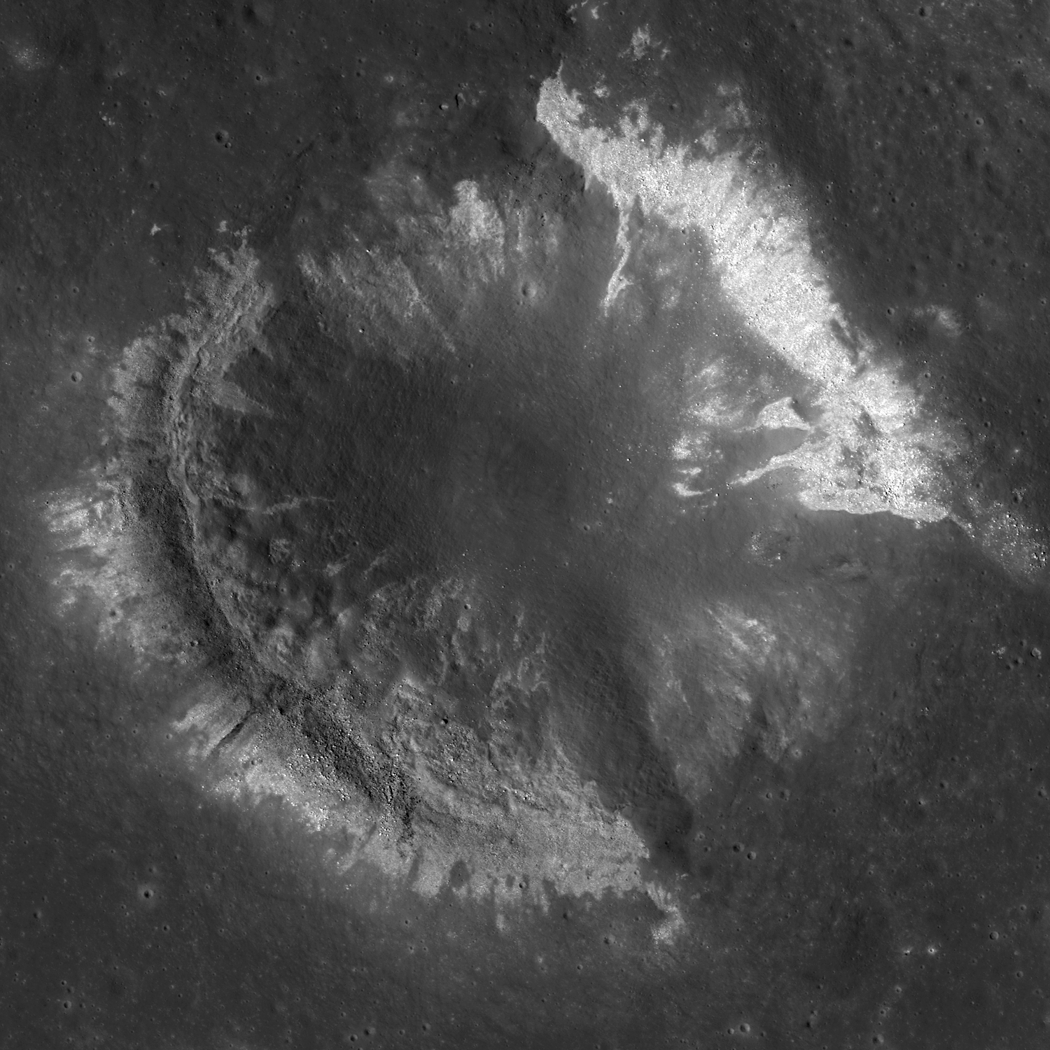
Today's Featured Image shows a striking impact crater in the northern hills of the massif. The crater exhibits an asymmetrical ejecta pattern, suggesting it to be the result of an oblique impact. The crater outline and ejecta distribution may also have been influenced by the uneven local topography. More geologically intriguing than this crater's shape, however, are the intermixed high and low reflectance materials excavated by the impact.

This wider field image from the same NAC frame shows an adjacent impact (northwest quadrant) to have excavated similar dark materials in the region; white square is the Featured Image location. Image is ~2.2 km wide [NASA/GSFC/Arizona State University].
The low reflectance materials (here seen as blocky) are suspected to be pyroclastic in origin, which speaks to the volcanic history of the Moon. Lassell crater itself (lower right in context image above) was described as being a source of pyroclastic materials since telescopic mapping efforts of the 1960s and '70s. The Lassell Massif is arguably close enough to this (and potentially other mare sources) to have received a share of these materials on the summits of its hills. Alternatively the central depressions on the massif may themselves be volcanic vents.

WAC mosaic context image. The white box outlines the area shown in the second image following above, field of view roughly 67 kilometers across [NASA/GSFC/Arizona State University].
While most lunar volcanism produced basaltic rocks, recent evidence is suggesting that Lassell Massif and other red spot areas are silica-rich, iron-poor volcanic deposits -- perhaps similar to the kind of volcanism we see with the Long Valley Caldera on Earth. While darker deposits tend to indicate an iron-rich material, their presence among silica-rich materials (which might seem like a geologic contradiction) may actually be suggestive of complex volcanism, where a variety of volcanic deposits are possible, and for which the Long Valley volcanics remain a good example.

What are the high reflectance materials seen distributed outward from the crater? Likely we are seeing ancient highland anorthositic material excavated from beneath an overlying volcanic deposit(s). What a fascinating spot for a future explorer!

From a 2010 demonstration, animation of separate LROC WAC observations of the geologically interesting Lassell Massif and crater group east of Lassell D, showing the latter's fresh ray system intruding from the west. This is more easily discerned under a high Sun while topography is easier to view under a mid-morning Sun in the east-northeast. The bright, widespread ejecta streamers from Lassell D alternates with a visible chevron affect by the Lassell D pressure front [NASA/GSFC/Arizona State University].
The next two Featured Image posts will include a brief discussion of this type of volcanism on the Moon, and explore some of the clues scientists are using to probe the Lassell Massif area. See the full NAC frame HERE. Other examples of pyroclastic deposits include DMD Excavations, Pyroclastic Trails, and Pyroclastic Excavation.

Monday, March 11, 2013

"Return to the Moon, but when and how?"

As with Real Estate on Earth, on the Moon location is everything. Shackleton crater (upper left) hosts a hoary frost clinging to its permanently shadowed interior, and the Moon's south pole resides on its rim. HDTV still captured by Japan's SELENE-1 (Kaguya) November 17, 2007; Malapert Massif - part of the mountainous rim of South Pole-Aitken basin - stands sentinel under a waning Moon, with east Asia, Australia, the western Pacific and Antarctica on an Earth waxing full visible is the background  [JAXA/NHK/SELENE].
David Darling
AmericaSpace

When Eugene Cernan, commander of the Apollo 17 mission, headed back up the ladder of the Lunar Module on December 14, 1972, he became the last human to date to walk on the Moon. Almost every U.S. Administration since that time has announced America’s intention to go back to our nearest celestial neighbor and establish a permanent presence there, but more than 40 years have gone by since the last bootprint was made in the lunar dust. What are the prospects for a return any time soon?

Read the full article, HERE.

Saturday, March 9, 2013

New 3D CLSE lunar flyover video: Schrödinger basin


David A. Kring, Ph.D.
Center for Lunar Science & Exploration (CLSE)


The Center for Lunar Science and Exploration added another video to its Atlas of Lunar Flyovers. In this new addition, we explore the floor of the Schrodinger basin.The direct link to the new flyover is HERE.

The Moon’s Schrödinger basin is the best preserved impact basin of its size.  Its broad flat floor offers several safe landing sites and the geology within the basin is extraordinary.  The two highest science priorities and over half of the science objectives outlined in the National Research Council (NRC) report The Scientific Context for Exploration of the Moon (2007) can be addressed with field studies and samples collected in Schrödinger basin.

Schrödinger basin CLSE landing study 'Site B' (yellow ellipse), well within the 10 km safety 'walk-back' distance of the an unnamed 6.8 km Copernican Age crater that presumably excavated deep into the basin's intact peak rings, depositing valuable samples near the crater rim. (Further details on this site will be the subject of a future post.) The site, in context with the larger basin, is marked with a yellow arrow below. LROC Wide Angle Camera (WAC) monochrome (643nm) observation M169698283C, LRO orbit 10142, September 3, 2011; angle of incidence 72.67° at 81.3 meters resolution, from 58.66 km [NASA/GSFC/Arizona State University].
The video highlights three features in the basin.  It begins with a flight along a fracture in the basin floor towards an immense volcanic vent of pyroclastic material.  Because of the in situ resource utilization (ISRU) potential of the pyroclastic material, this vent was a target of the Exploration Systems Mission Directorate (ESMD) portion of the Lunar Reconnaissance Orbiter (LRO) mission.

The notably darker material surrounding Schrödinger basin's distinctive pyroclastic vent. Another landing site (green arrow, in an image showing the entire basin interior floor) is proposed near upper center right in this oblique LROC Narrow Angle Camera (NAC) field of view. LROC NAC mosaic M121415248LR, LRO orbit 3026, February 21, 2010; angle of incidence 81.66° (spacecraft slew -65.65° off nadir) rough resolution 3.7 meters from 53 km [NASA/GSFC/Arizona State University].
The flyover then turns towards the towering and mountainous peak ring that contains rock exposures of material uplifted from the mid- to lower-crust by the basin-forming impact event.  The flyover then sweeps back towards the pyroclastic vent over an intervening plain of melt-bearing impact lithologies.  Samples of that material can be used to determine the age of the Schrödinger basin and, thus, help test the lunar cataclysm hypothesis.

Related Posts:
Amundsen crater: CLSE lunar landing site study (February 5, 2013)
Scarps in Schrödinger (September 28, 2011)
Sampling Schrödinger (August 17, 2011)
A review of all things Schrödinger (August 31, 2010)
LOLA: Schrödinger basin (July 17, 2010)
Craters on the Schrödinger pyroclastic cone (April 24, 2010)

LROC WAC 100 meter monochrome global mosaic shows the 312 km-wide Schrödinger basin, a prominent feature of the far southern far side latitudes and stand out increasingly as a location where many high-priority lunar exploration science goals might be accomplished. The area includes smooth and rough plains, basin wall material, hummocky terrain, intact peak rings, mare, dark explosive volcanic material and ridged terrain. CLSE Landing Site Study Site A (green arrow) and Site B (yellow arrow) are shown at much higher resolution in the images further above [NASA/GSFC/Arizona State University].

Friday, March 8, 2013

Impact melt on the floor of Rümker E

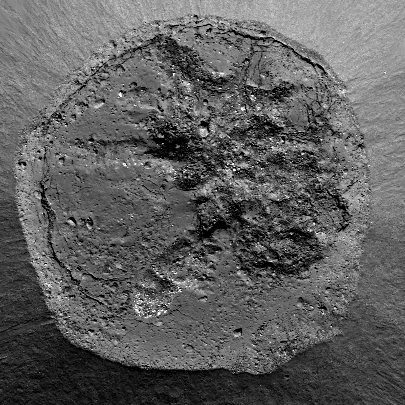
Contact between wall, with debris flows, and the impact melt lens inundating the floor of Rümker E, immediately southeast of the landmark Mons Rümker ridge extrusion mound in north Oceanus Procellarum. Area detail covered in the LROC Featured Image released March 8, 2013. LROC Narrow Angle Camera (NAC) observation M122591558L, spacecraft orbit 3200, March 7, 2010; angle of incidence 42.68° at 0.5 meters resolution from 40.63 km [NASA/GSFC/Arizona State University].
LROC Featured Image, March 8, 2013: Close up on the full width of the impact melt deposit on the floor of Rümker E, in an approximately 2 km wide field of view from LROC NAC M1101573334L, LRO orbit 14668, September 6, 2012; angle of incidence 41.16° at 1.13 meters resolution, from 152.92 km  [NASA/GSFC/Arizona State University].
Sarah Braden
LROC News System

Imagine a quiet afternoon on the lunar surface about 1 billion years ago. Suddenly, the ground shakes due to the shock wave from a nearby impact.

You see rock and dust burst away from the ground on ballistic trajectories, and some large chunks of material contain so much energy from the impact, they are glowing with heat.

Some of the molten rock splashes outside the rim, but most remains on the floor of the newly formed crater, creating an impact melt deposit.

The crater Rümker E (38.620°N, 302.881°E) is a simple Copernican-aged crater with a diameter of 6.96 km.

Two LROC Wide Angle Camera (WAC) mosaics show different sun angles. Above, the sun angle is higher, so the high reflectance rays of the crater are more visible, and below the sun angle is lower, emphasizing the morphology of the surface [NASA/GSFC/Arizona State University].
Impact melt in the crater floor is fresh with common features such as fractures, boulders, and mounds. The fractures are mostly located around the edges of the impact melt deposit and formed either as the impact melt cooled, or after cooling during the stage of crater modification due to stresses in the crater floor. Over time the granular material falling down the crater walls will slowly cover more and more of the impact melt deposit, decreasing its diameter. Compositionally, the impact melt is a combination of the rocks present in the target material. In this case, the target material is mostly mare basalt.

Rümker E in relation to Mons Rümker, a wide volcanic shield mound showing sighs of long-term episodic, if not particularly violent, periods of activity; a extraordinary formation easily seen at high angles along the telescopic line of sight from Earth. LROC WAC monochrome (643nm) mosaic [NASA/GSFC/Arizona State University].
Explore the entire NAC frame, HERE.

Check out these previous posts for more examples of beautiful impact melt features:
Lineations on the Melt
Dynamics of Molten Rocks
Sunny Side Up

The wrinkled morphology and ridges of north Oceanus Procellarum, including compositional differences between the mare terrain and Mons Rümker (above left from center), are more difficult to detect when the Sun is high, but when the terminator passes and the Sun is low, the anatomy is stark. from HDTV still captured by Japan's lunar orbiter SELENE-1 (Kaguya) in 2008 [NASA/GSFC/Arizona State University].

Thursday, March 7, 2013

The Moon's Permanently Shadowed Regions


New video presentation from NASA-Space Visualization Studio (SVS) at Goddard Space Flight Center (GSFC) combines data from instruments on-board Lunar Reconnaissance Orbiter (LRO) to demonstrate the dynamics of the Moon's permanently shadowed regions (PSRs).

Details: LRO peers into Permanent Shadows (SVS)

Wednesday, March 6, 2013

Wrinkle Ridge vs. Impact Crater

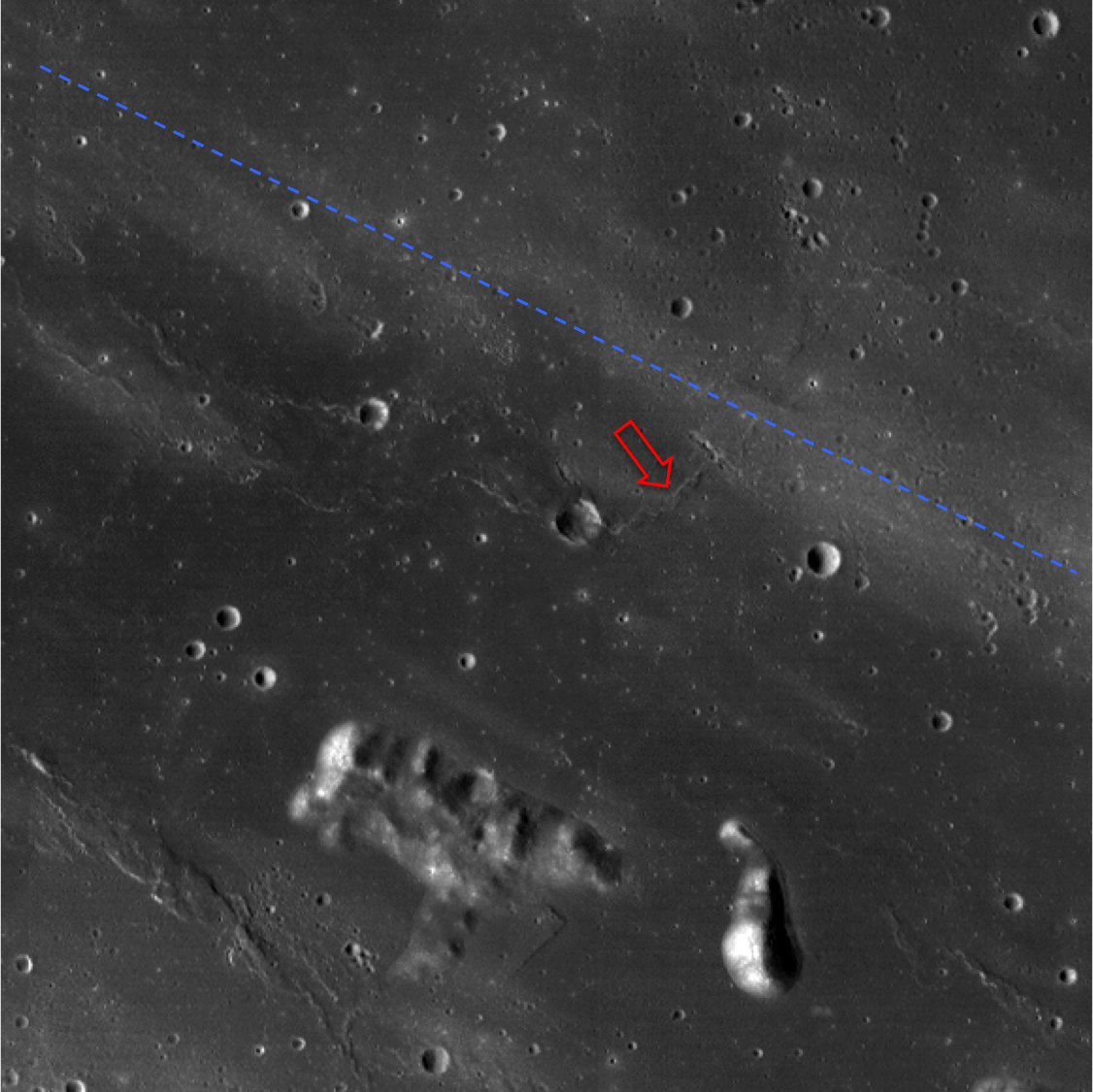
An impact crater, subsequently modified by a wrinkle ridge in Mare Imbrium. Field of view 3.2 meters wide from LROC Narrow Angle Camera (NAC) observation M1114391184R, LRO orbit 16466, February 1, 2013; 1.23 meters resolution [NASA/GSFC/Arizona State University].
Sarah Braden
LROC News System

Stratigraphic relationships in today's Featured Image tell a story of complex geologic events on the lunar surface.

Planetary geologists interpret images taken from orbit and piece together a narrative. Initially a bolide impacted the lunar surface, creating a crater.

Subsequently mare basalt flows buried parts of the impact crater. In the above image you can see darker material around the edges of the crater's rim and also areas where mare basalt material covered parts of the rim and the crater interior. Finally, tectonic deformation created a wrinkle ridge which is better seen in the context image and topography below. Boulders from the wrinkle ridge fell into the impact crater where the edge of the wrinkle ridge intersects with the crater's rim (upper right hand corner of the Featured Image). This impact crater has seen better days!

LROC Wide Angle Camera (WAC) context image. The crater from the Featured Image is in the center (SW of the arrow), and the red arrow denotes the wrinkle ridge. The dotted blue line shows the path of ejecta (ray) from Copernicus. Image field of view is 40.8 km across [NASA/GSFC/Arizona State University].
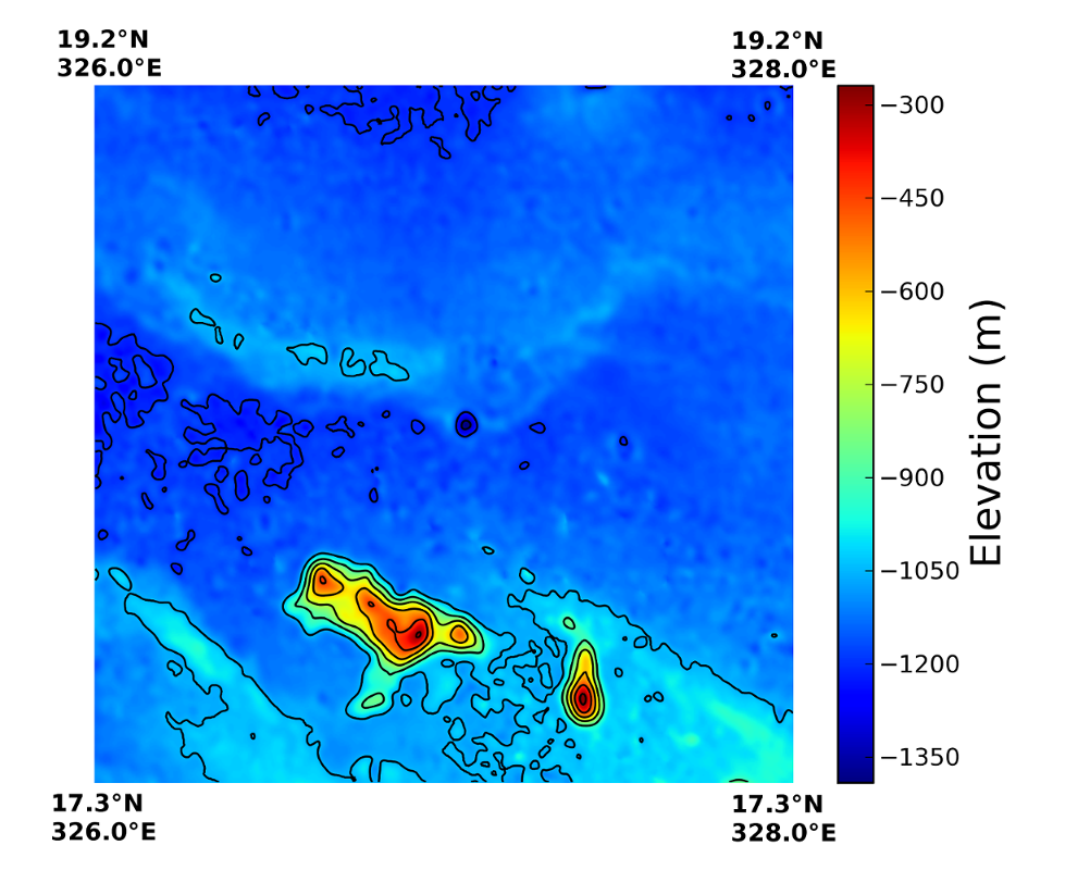
This region is located south of the crater Brayley D at the edge of Mare Imbrium. The crater in the Featured Image is ~2 km in diameter, and ~250 m deep (located at 18.240°N, 327.06°E). The wrinkle ridge is easier to see in the colorized topo image below. It extends from east to west across the mare.

LROC WAC topography showing the same region, contour interval is 140 meters elevation [NASA/GSFC/Arizona State University].
Explore the entire NAC frame to see more of the wrinkle ridge and surrounding mare, HERE.

Related Posts:
Posidonius Y
Boulders in the Sea of Serenity
Up and Down / Back and Forth
A Wrinkly Crater

Tuesday, March 5, 2013

Copernicus collapse pit

Collapse feature in the impact melt on the floor of Copernicus, field of view 430 meters, from LROC Narrow Angle Camera (NAC) observation M168333206L, LRO orbit 9941, August 18, 2011; resolution 40 cm per pixel from 25.4 kilometers. Originally posted to illustrate "Failed Skylights of Copernicus," January 24, 2012 [NASA/GSFC/Arizona State University].
Sarah Braden
LROC News System

A fresh collapse feature within the impact melt floor of Copernicus crater is 330 meters across (that's about 3 American football fields wide!). At one point the impact melt in this area was flat, but then the area collapsed forming the feature here (located at 10.204°N, 339.998°E). The rim of the depression is still very fresh with outcrops and boulders.

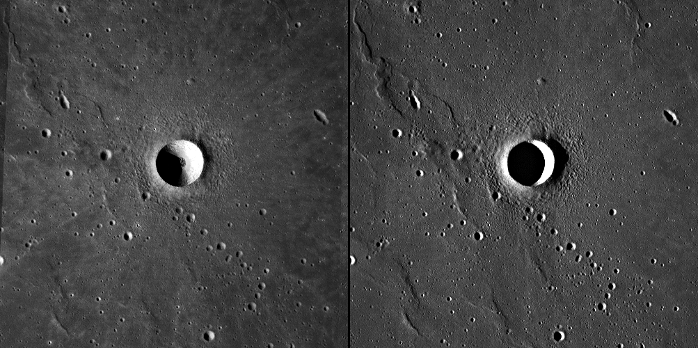
An estimate of the feature's depth is approximately 50 meters, based on shadows from another NAC image of the same area. There are a few possible causes for the collapse.

A subsurface void may have formed as the impact melt flowed and cooled. Subsurface voids occur when melt emplaced shortly after the impact drains away deeper into the impact cavity. Perhaps a small bolide impacted the surface and instigated the collapse of the structurally weak void. Alternatively, the collapse might be due to seismic shaking from moonquakes disturbing the weak section of the melt deposit.

Oblique view of the featured collapse pit, from well to the east of Copernicus; a montage of the left and right frames of LROC NAC observation M193025138 (thumbnail at bottom), orbit 13472, May 30, 2012. Spacecraft slewed from 63.11° from nadir [NASA/GSFC/Arizona State University].
This collapse feature is much larger in diameter than the mare pits: the Mare Ingenii pit is about 130 meters in diameter, the Marius Hills pit is about 65 meters and the Mare Tranquillitatis pit is around 100 meter across.

Pits in mare basalt may have formed when a portion of a lava tube collapsed. The subsequent pit is a skylight that leads into the intact lava tube. Impact melt pits are common within impact melt deposits like the one here in Copernicus, however the depression in the Feature Image is larger in diameter than average impact melt pit. Perhaps in this case the subsurface void was larger, or the surface layer of impact melt was structurally weaker, resulting in a larger collapse area.

Arrow marks location of the featured collapse pit, near an north-south contact between distinct impact melt types, easier to visualize, perhaps, in color and other images highlighting lunar surface albedo. LROC Wide Angle Camera (WAC) monochrome mosaic M147109260C, orbit 6813, December 16, 2010; resolution 60 meters from 43 km, angle of incidence 78°
A previous Featured Image, "Copernicus Seen Looking Straight Down," featured a mosaic of Copernicus's floor (9.62°N, 339.92°E, 93 km in diameter), but today's Featured Image offers much higher resolution.

Explore the entire NAC frame for more high resolution impact melt deposits, HERE

Related Images:
Copernicus Seen Looking Straight Down
Copernicus Central Peak
Natural Bridge on the Moon!
Impact Melt Pit
Failed Skylights of Copernicus

Monday, March 4, 2013

New oblique views of Gruithuisen Domes

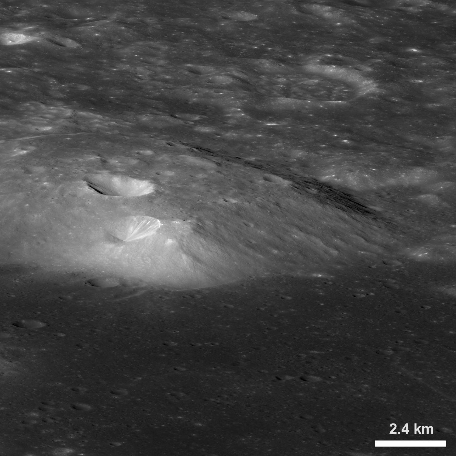
An oblique view of the northern portion of the Gruithuisen Gamma volcanic dome, from the northwest. From a new LROC Narrow Angle Camera (NAC) mosaic M1106087898LR, LRO orbit 15300, October 28, 2012; overall resolution 4.9 meters per pixel [NASA/GSFC/Arizona State University].
Sarah Braden
LROC News System

The last LROC Featured Image post on the Gruithuisen Domes featured some of the earliest Narrow Angle Camera (NAC) coverage of this amazing region.

Now LROC brings you an even more dramatic view of these volcanic domes from an oblique angle (viewing from East to West), from an altitude of 154 km (96 miles) above the lunar surface.

Located along the mare/highlands boundary, on the northeast border of Oceanus Procellarum (36.6°N, 319.9°E), the three Gruithuisen domes Gamma, Delta, and Northwest (NW) are primary examples of lunar silicic volcanism.

A thumbnail image of the 20376 x 6728 oblique NAC montage users can zoom into HERE. The crater Gruithuisen B is 9 km in diameter (north is to the right) [NASA/GSFC/Arizona State University].
Field of view seen at an oblique angle sketched out (arrows) on a photometric work-up of an LROC monochrome Wide Angle Camera (WAC) overview by Maurice Collins, originally presented as a Lunar Picture of the Day (LPOD), September 27, 2010 [NASA/GSFC/Arizona State University].
Silicic volcanism is relatively rare on the Moon. The Gruithuisen Domes pre-date the lunar mare in this region, so some portion of these domes has been covered by mare basalt, although there are also contacts with the older highlands material. Silicic volcanism might have been more widespread during the Moon's early history, however, any evidence for that may be buried beneath the maria. We know that the composition of the Gruithuisen Domes are different from that of the mare and the highlands from Earth-based telescopes, Lunar Prospector gamma-ray spectroscopy data, and Clementine multispectral data. The Gruithuisen Domes are characterized by relatively high reflectance and strong absorptions in the visible and ultraviolet. The Domes are also low in iron and titanium abundance compared to the lunar maria. New data from the Diviner instrument on the LRO spacecraft confirmed that the Gruithuisen Domes are silicic.

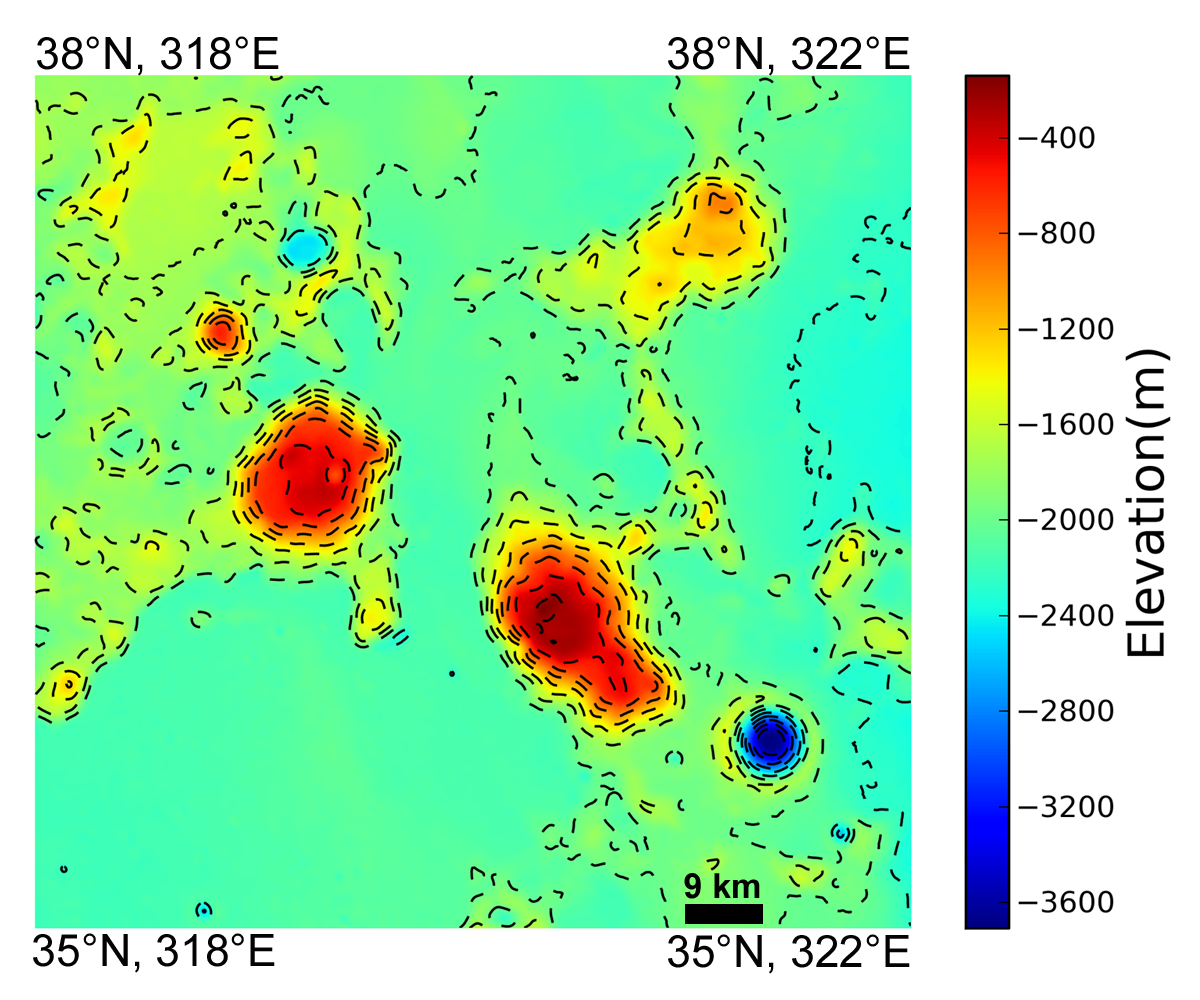
Colorized topography of the Gruithuisen Domes region derived from the 100 m/pixel LROC WAC DTM. Contour line interval is 220 meters [NASA/GSFC/Arizona State University].
Experience the full resolution oblique image HERE.

Related LROC Featured Images:

Gruithuisen Domes - Constellation Region of Interest
Morphology of lunar volcanic domes
LROC NAC DTM Viewer Gruithuisen Domes (ROI) 1 - 2 - 3 - 4 - 5
Hansteen alpha yields some of its secrets
Silicic volcanism on the Moon
Compton Belkovich - Constellation ROI
Hortensius Domes - Constellation ROI