Friday, February 4, 2011

New View of Apollo 14: 40th Anniversary


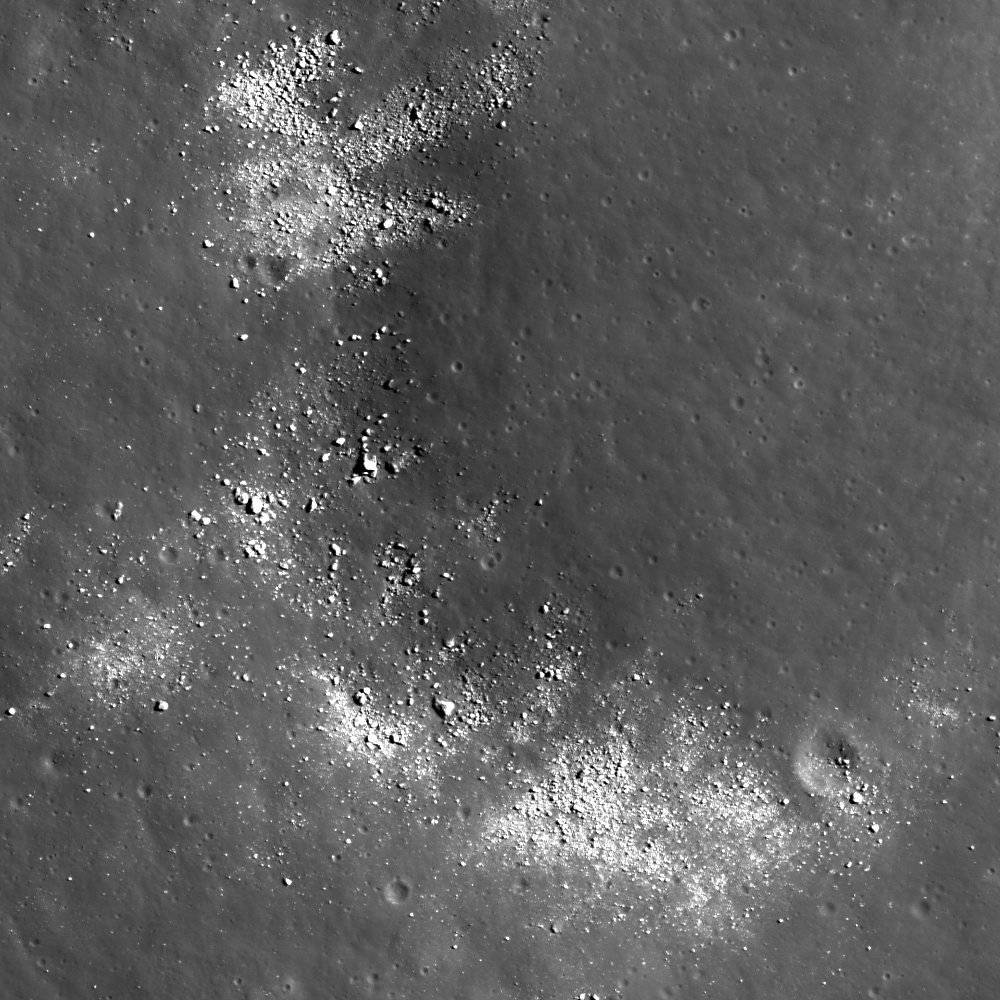
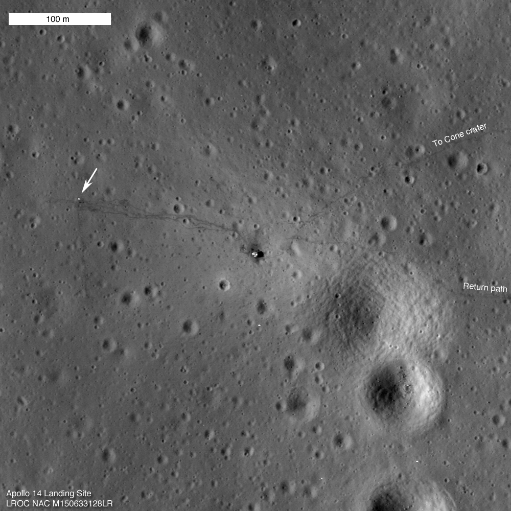
LROC Narrow Angle Camera (NAC) observation M150633128 of the Apollo 14 landing site acquired January 25, 2011 (LRO orbit 7334; resolution = 0.5m). The Descent Stage of the lunar module Antares is at center and the foot paths trailed by Shepard & Mitchell in February 1971 seem totally undisturbed since their departure forty years ago this weekend (field of view 500 meters). Experience the full-sized (1000x1000) LROC Featured Image released February 4, 2011 HERE [NASA/GSFC/Arizona State University].

Mark Robinson
Principal Investigator
Lunar Reconnaissance Orbiter Camera
Arizona State University


The LROC Narrow Angle Cameras continue to image the Apollo landing sites as the mission progresses. Every time LRO passes overhead the Sun is at a different position so each image gives a different perspective. Repeat imaging also serves LROC cartographic goals. Since the position of the lunar modules and other pieces of hardware are very accurately known the LROC team can check the accuracy of the mission-provided ephemeris.

Think of the Apollo sites as benchmarks put in place four decades ago for the LROC team!
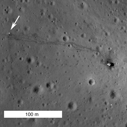

Close-up showing the Apollo 14 Lunar Module's Descent Stage (right) and Apollo Lunar Surface Experiment Package (ALSEP - arrow) with tracks between the two landmarks by Shepard & Mitchell still fresh and distinctive almost precisely 40 years later. In that interval since their departure the foot prints and Apollo 14's deployed materials endured 534 lunar days and nights of relentless exposure, adding to their immeasurable value as sentinel recorders of the lunar environment [NASA/GSFC/Arizona State University].

The Apollo 14 astronauts explored the surface of the Moon on February 5th and 6th, 1971, 40 years ago this weekend. Much was learned during the Apollo missions, yet most of the history and geology of the Moon remains a mystery.

When will we return to the Moon?


Apollo 14 Post EVA view by Edgar Mitchell from inside Antares looking west toward the ALSEP station. LROC PI Mark Robinson suggests matching Edgar Mitchell & Alan Shepard's tracks in this photograph with those in the new LROC NAC view swept up from LRO orbit overhead on January 25, 2011 - forty years later. View the full-resolution high-defintion version of Mitchell's photograph HERE [AS14-66-9338 - NASA/Apollo Surface Journal].

From the Apollo Surface Journal, Apollo 14 Image Library (Magazine 66) "
Ed Mitchell took this splendid picture after he and Al Shepard jettisoned the PLSSs in preparation for launch. Of particular interest are the tracks made by the crew and the MET during the traverse to the ALSEP deployment site and during the return to the LM. Apollo 17 astronaut Jack Schmitt speculates that the descent plume sweeps away the fine particles of soil, leaving a surface dominated by small rock fragments that reflect sunlight from the down-Sun direction and make the surface look lighter in color than normal. In places where the surface is disturbed, the normal reflectivity of the surface is restored. Whatever the detailed explanation for this phenomenon, it is related to the fact that, from orbit, the area immediately surrounding a LM looks noticeably lighter in color. The ALSEP Central Station is about 180m from the LM. Note the excursions the crew made around the rimless crater in the foreground and the large depression in the middle distance that they traversed in both directions. Without the visual clues provided by the tracks, the depression is not easy to pick out in this down-Sun photo. Note that the flag is now pointing on an azimuth of about 335 and undoubtedly moved from it prior pointing of about 120 as a result of the cabin depressurization done for the jettison."

No one to ask for directions: Apollo 14 lunar module pilot Edgar Mitchell finds the "ground truth" of hiking on the Moon, that things can look very different on the surface than from Lunar Orbiter photography from orbit, and he surveys a map while looking for landmarks. Meanwhile Alan Shepard takes his picture near the end of their unsuccessful ascent up the gentle slope to Cone Crater, at Fra Mauro, February 1971. (It was the first time an Apollo expedition had journeyed beyond view of their spacecraft) [AS14-64-9089HR/NASA/ASJ].


A 'true-color' HDTV orbital view, from Japan's SELENE-1 (Kaguya), of the ancient Fra Mauro crater group and material spilled onto this area, south of Copernicus, from the epoch-marking basin-forming impact formimg Mare Imbrium to the northwest ~3.8 billion years ago. The landing site of Apollo 14 is located in the low hills north of the largest of these craters, at upper center. Click HERE for the full-sized original image release [JAXA/NHK/SELENE].

Journey to the Center of the Moon


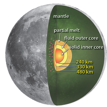
New interpretation of the lunar interior (from Weber et al., 2011, Science 331, 309-312)

Paul D. Spudis
The Once & Future Moon
Smithsonian Air & Space

A recently published science paper presented results of a re-analysis of seismic (moonquake) data sent to the Earth from a network emplaced by the Apollo astronauts 40 years ago. The scientists processing the old data found that the Moon may have more than a simple core – it may have a layered, partly liquid metallic core.

Why is this important? Scientists have known for many years that the Earth has a layered interior structure. The outermost layer, called the crust, is the only part of the Earth directly accessible to us for study. The crust varies in thickness, ranging from a few kilometers in the ocean basins to over 20 km in continental areas. The next zone down is called the mantle. The mantle is very thick – almost 3000 km. It is made up of a dense, iron- and magnesium-rich rock type called peridotite. Partial melting in the mantle is the source of basaltic magma that erupts to make up the floors of ocean basins worldwide. The innermost part of the Earth is the core, comprised mostly of metallic iron and nickel, and over 3000 km in radius. The outer layer of the core is liquid, but the enormous pressure that contains the inner core keeps it solid.

The Earth’s core is electrically conducting as the rotation of the Earth induces currents within it. It is thought that these electrical currents are responsible for the dynamo that generates the magnetic field of the Earth. Because most of the Earth’s iron is contained in the core, we know that in bulk composition, the Earth is made from chondrites, the same stony material found as primitive meteorites in space. Thus, understanding the core is relevant to the origin of its magnetic field and the internal structure and bulk composition of the Earth.

For these reasons, we are interested in the possibility of a core within the Moon. Even before we went to the Moon, we understood that an internal structure similar to Earth was not likely. A property called moment of inertia told us in broad terms that, unlike the layered structure of Earth, the Moon was more or less homogeneous inside. The moment of inertia indicated that any core inside the Moon must be smaller than a couple of hundred kilometers at most (the Moon’s radius is 1740 km).


The Apollo 12 Apollo Lunar Surface Experiment Package (ALSEP) after its deployment in Oceanus Procellarum, November 19, 1969. Among the instruments set up by Conrad & Bean was the Passive Seismic Experiment (PSE). The Apollo ALSEP assets were kept powered by radioisotope thermoelectric generators and data continued to be collected until the project was defunded in 1977, leaving only three laser range reflector arrays as the only remaining Apollo assets contributing new science until the arrival in orbit of LRO in July 2009 [AS12-67-6817-Conrad/Apollo 12].

Seismometers, deployed on the Moon as part of a surface network during the Apollo missions, operated for over seven years collecting data on tremors within the Moon. Because certain rocks have known physical properties (e.g., density), we use the velocity of seismic waves in an indirect way to infer the presence of these rock types and physical structure. From our initial analyses of these data, we determined that the Moon had a fairly thick crust (from 50-80 km, more than twice the thickness of Earth’s crust) and a very thick mantle, almost the remainder of the lunar radius.

The question of the existence of a lunar core remained uncertain. One moonquake resulting from a fairly large impact on the far side of the Moon a couple of years after the Apollo missions had ended produced a signal that suggested the presence of a small core (less than 400 km radius). Moreover, because seismic waves come in two varieties – P-waves, or compression (or sound) waves and S-waves (shear waves, which cannot propagate through liquids) – the partial suppression of S-waves through the center of the Moon during this event suggested that the lunar core might be partly liquid.


The Apollo 14 S-IVB booster (S-IVB-509) was 17.8 meters tall, 6.6 meters wide and weighed about 14,000 kg. It was launched January 31, 1971, and after extraction of the Lunar Module Antares, the S-IVB was directed to dump its remaining fuel directed toward an impact the Moon February 4, 1971. (From "Apollo 14 S-IVB Impact Crater," Mark Robinson, October 8, 2009) "The Apollo impact velocity was 2.54 km/sec at an angle of 69° from the horizontal along a heading of 103° (west to east). The S-IVB had a mass of 14,016 kg at the time of impact and impact energy was 5.54 x 10\10 Joules (equivalent to just over 10 tons of TNT). The signal from the impact was recorded on the Apollo 12 seismometer (PSE) and rebounded throughout the Moon for 3 hours." [NASA/ARC/NLSI].

But this result was so uncertain that few lunar scientists actually believed it. They proceeded to try and constrain the dimensions and composition of a lunar core through other means. A core may be important in the generation of an early global magnetic field that some of the lunar samples seems to indicate (the current Moon has no global field). By carefully measuring the ways in which the magnetic field of the Sun and Earth is modified when the Moon passes through it (as it does during its orbit around the Earth), it was thought that it might be possible to “sense” the presence of a lunar core by measuring these deviations. Results indicated that the core of the Moon had to be small (less than 400 km in radius) and probably made of iron sulfide (FeS).

After seven years of operation, the Apollo seismic net was turned off to save money. Up until it was turned off, we had received a large amount of data but processing it was extremely difficult. The Apollo instruments, although sensitive, were very noisy and not well coupled to bedrock as are seismometers on Earth. Fortunately, faster and more capable computers, along with new techniques to process and analyze noisy data, were developed. And a new generation of scientists came forward to re-examine the old seismic data to see if anything could be discerned from it.

The new results are surprisingly detailed. Not only do these researchers think they have detected a core inside the Moon, but a core with three separate layers – an inner solid core and outer core, very similar in structure to that of the Earth, but with the added wrinkle of a partly molten outermost layer. The entire core is almost 500 km in radius, slightly larger than the diameter inferred from deep magnetic sounding.


LROC Observation M111762553R, LRO orbit 1604, November 2, 2009, from 43.5 km, resolution 49cm/p, solar incidence 31.3° Apollo 14 S-IVB impact at 8.179°S, 333.969°E (from from "LROC Coordinates of Robotic Spacecraft," Samuel Lawrence, April 5, 2010) [NASA/GSFC/Arizona State University].

The presence of currently molten core inside the Moon is rather startling; even the earlier idea about a partly molten zone was viewed askance by most lunar students. But this new idea has revived concepts about a magnetic core dynamo inside the Moon, generating a global field early in lunar history. Such a dynamo might explain a lot about the remnant magnetic fields measured in some of the returned lunar rocks. But there is no obvious reason why such a field would suddenly stop being generated.

Even though the old Apollo network data may still be mined for information, to fully understand lunar structure and history we must emplace a long-lived, global network of new instruments to fully characterize the interior of the Moon. Although studies are underway to determine how this might be accomplished, deployment of such a network is difficult to achieve by robotic spacecraft alone and long life on the Moon may require a nuclear power supply. Each and every time we start believing that we understand our Moon, a new discovery raises even more questions.

Thursday, February 3, 2011

Mendeleev in Full


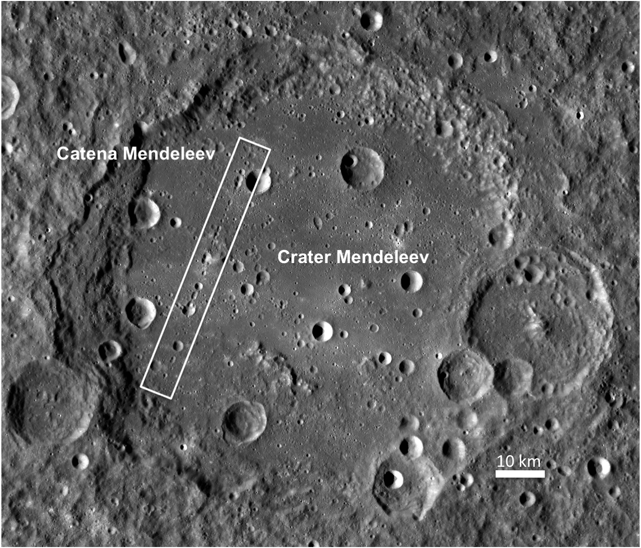
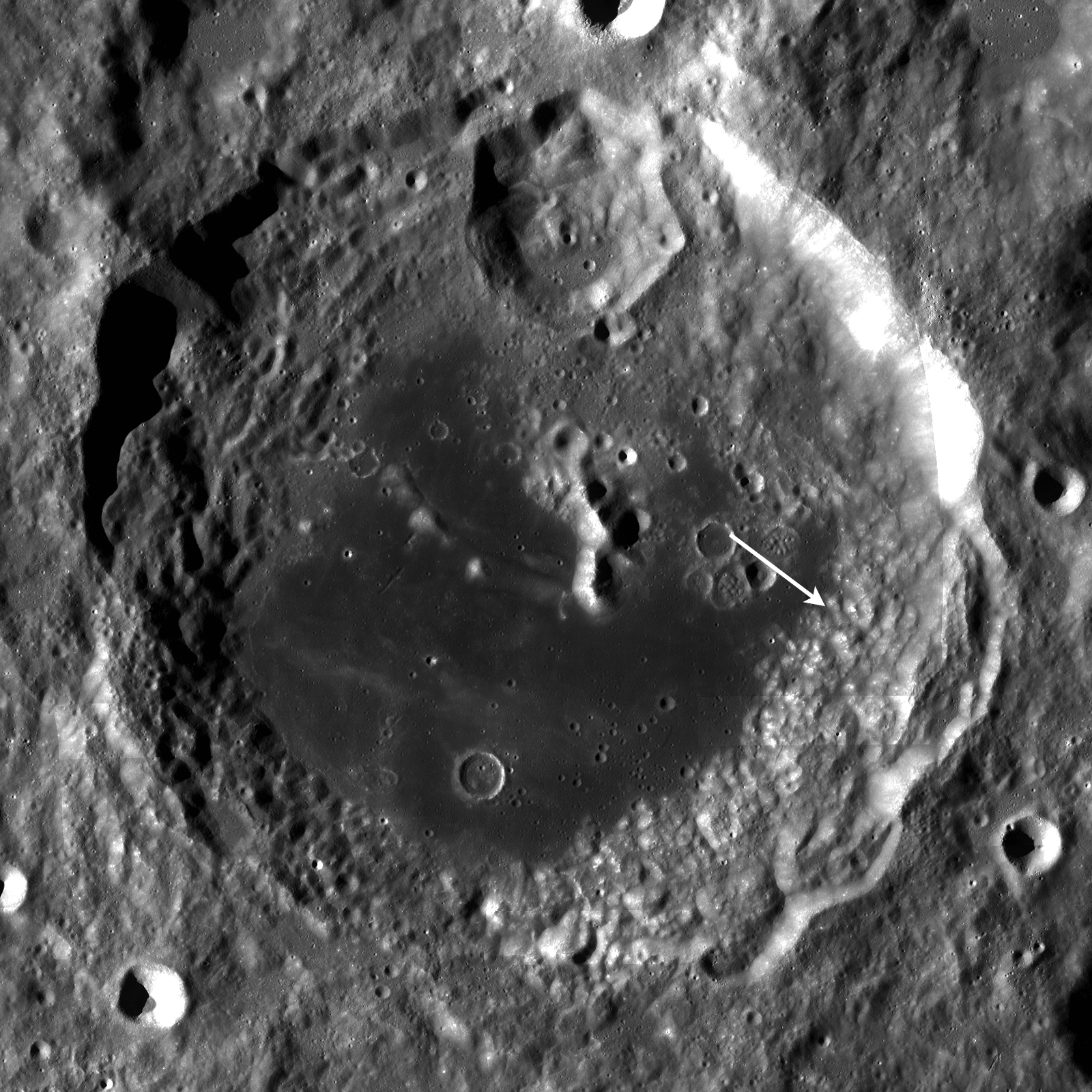
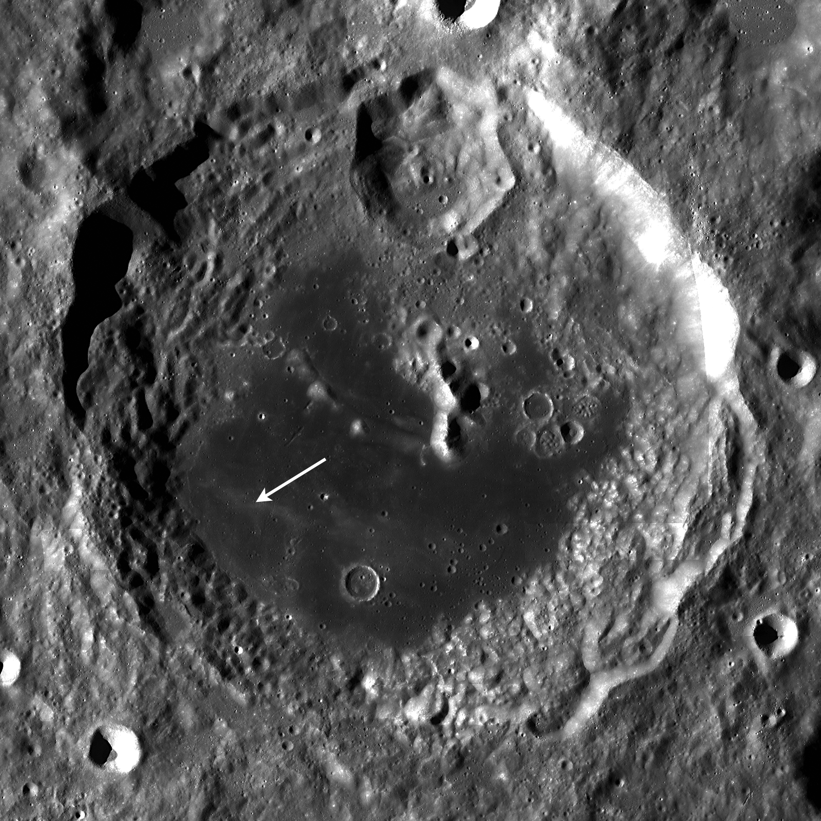
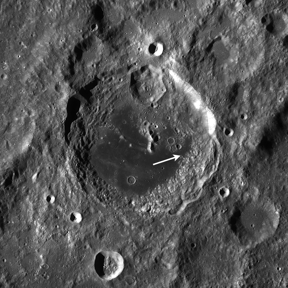
A LROC Wide Angle Camera (WAC) 100 meter/pixel monochrome mosaic released February 3, 2011, shows all of Mendeleev (313 km in diameter) in a full-sized dramatic view available HERE. The white rectangle marks the location of Catena Mendeleev, highlighted in greater detail HERE and below [NASA/GSFC/Arizona State University].

Sarah Braden
LROC News System

Mendeleev crater (named after Dimitri Mendeleev, the inventor of the periodic table of elements) is a very large, Nectarian-age crater on the lunar farside (5.7°N, 140.9°E). Approximately 313 kilometers in diameter, it is almost large enough to be a small basin. The interior contains many younger craters, including Catena Mendeleev, but also features a very smooth floor filled in with a light plains material. In general, this material is characterized by its smooth surface and intermediate albedo (brighter than basaltic mare material, but not as bright as highlands material). Light plains are found elsewhere on the Moon, most notably in the Cayley formation, the Apollo 16 landing site. Light plains are usually thought to be emplaced as large scale grounding flows of ejecta from large basin forming impacts. However details of this formation mechanism are still not well understood.


A fanciful view of the newly-released LROC WAC mosaic, tapered into the lunar digital elevation model available to users of Google Earth (>v.5). In the foreground left Richards crater (7.7°N, 140.1°E) is approximately 9 km in diameter [NASA/GSFC/Arizona State University/USGS/JAXA].

Explore the entire WAC mosaic here!

Related Posts:
Hunting for Ancient Lunar Impact Basins
Mare Frigoris


In 2007, Japan's robust first lunar orbiter SELENE-1 ("Kaguya") took high color High Definition television views from orbit, including this still of Mendeleev from around 100 kilometers above and several hundred to the south, as all of the 313 km crater lingered momentarily on the orbital horizon. Click HERE to see the full-sized image [JAXA/NHK].

Wednesday, February 2, 2011

Inside Catena Mendeleev


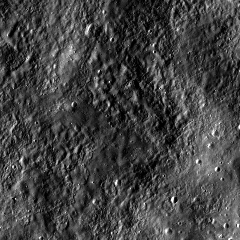
Texture on inside wall of a crater in the Catena Mendeleev, a linear crater chain located inside the 313km Mendeleev crater (5.7°N, 140.9°E), detail from LROC Narrow Angle Camera observation M113038958R, solar illumination incidence angle 46°, image resolution 0.5 m/pixel; LRO orbit 1792, November 16, 2009. View the full-sized original LROC Featured Image, HERE [NASA/GSFC/Arizona State University].

Sarah Braden
LROC News System

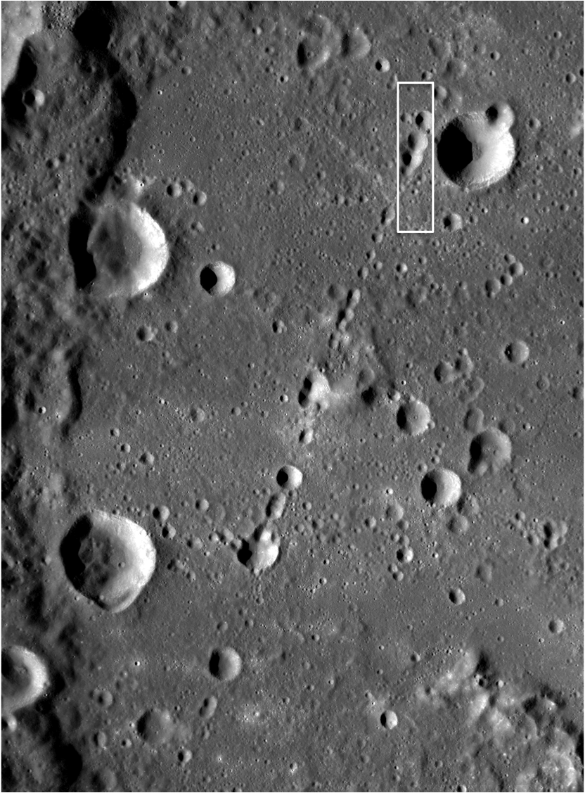
Catena Mendeleev is a linear crater chain probably formed by the impact of fragments (called 'secondaries' by planetary scientists) that were ejected by the impact that formed Tsiolkovskiy Crater, 850 kilometers to the southwest of Mendeleev. Crater chains form from secondary impacts ejected radially from their parent impact.

Today's Featured Image shows the rough and smooth textures on the inside of one of these secondary impacts. Secondary craters in a chain are often elongate in shape, with irregular rims. Secondary crater chains tend to occur in a zone immediately surrounding a large primary crater. However, larger impacts can move significant amounts of ejecta, including crater chains, far from the primary crater, as we see here at Catena Mendeleev.


LROC Wide Angle Camera 100 m/pixel monochrome mosaic, annotated with a white box marking the location of LROC NAC observation M113038958 field of view, centered at 7.67°N, 139.62°E, within Mendeleev Crater [NASA/GSFC/Arizona State University].


Backing away further from the field of view above allows for even more context, using the LROC WMS Image Map. The full-extent of the relatively flat interior of 313km-wide Mendeleev in comparison with the rolling highlands typical of the lunar farside comes into view [NASA/GSFC/Arizona State University].

Browse the full NAC frame to explore the craters in Catena Mendeleev!

Related Posts:
Chain of secondary craters in Mare Orientale
Stream of Secondary Craters

Tuesday, February 1, 2011

Farside Stratified Ejecta Blocks


A stratified ejecta block around an unnamed fresh crater on the far side of the Moon, LROC Narrow Angle Camera observation M110757216R, LRO orbit 1456, October 21, 2009 (frame centered near 13.13°N, 127.61°E). Solar incidence angle is 24°, scale is 0.58 m/px [NASA/GSFC/Arizona State University].

Sarah Braden
LROC News System

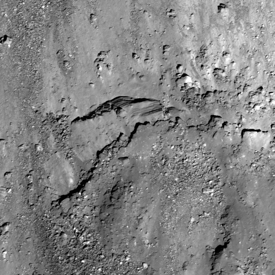
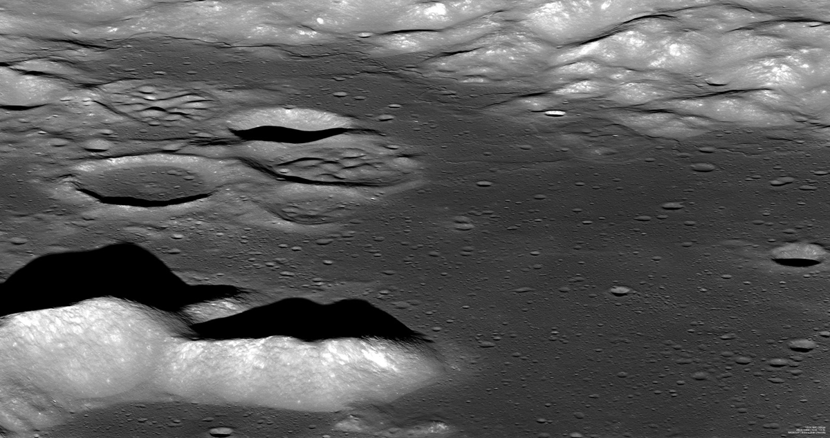
An unnamed, young Copernican crater (about 8.6 km in diameter) northeast of crater Meshcherskiy, has a diverse collection of impact ejecta features. In today's featured image we see evidence for stratified materials in the ejecta blanket of the crater. This particular block, about 170 meters across (approximately two football fields long), might have formed through the impact process, or perhaps the stratified layers are consolidated (compressed) regolith. During an impact, material is thrown out of the crater cavity in sheets of material called ejecta. With the right conditions, the sheets of ejecta could form the layers of the block seen here. It is also possible that the layered material existed before the impact. The simplest explanation is that the layers we see here are actually linear stress fractures in a continuous block, due to the strength properties of the rock. Can you find similar layered rocks in other NAC images elsewhere on the Moon?


Another 80 meter-long section of ejecta, from the same crater and NAC frame appears also to have stratified layer (left side of image) [NASA/GSFC/Arizona State University].


Backing away from LROC NAC M110757216R shows debris fans falling back into the crater's interior. This close-up view of this relatively "fresh" (Copernican) crater provides the opportunity to examine lunar features before their distinctive rougher edges are pulverized by relentless bombardment by even fresher impacts, near and far, large and microscopic [NASA/GSFC/Arizona State University].


Context for the the dramatic LROC NAC frame M110757216, centered near 13°N, 127°E, 750 kilometers southwest of Mare Moscovienese [LROC WMS Image Map/Arizona State University].

Browse the rest of the ejecta blanket in the NAC frame.

Related Posts:
Recent Impact
Impact Melt Flows on Giordano Bruno

Students study lunar samples

From Album LP4
Trinity Academy eighth-graders Gabrielle Fatula and Steven Wargo engage in a mock tug-of-war over a display of Apollo lunar samples on loan from NASA for Catholic Schools Week at Trinity Academy in Shenandoah, Pennsylvania. The display, together with meteorite samples and student-made displays will be open for public viewing Wednesday, February 2, from 6 to 8 p.m.

John E. Usalis

The students at Trinity Academy in Shenandoah won't have to go to the moon to see lunar soil and rocks. The items came to them.

Thanks to Trinity science teacher Michael Kowker, samples of the lunar material collected by the astronauts of the Apollo space program will be on display to the public Wednesday from 6 to 8 p.m. at the school as part of Catholic Schools Week.

Protected in a plastic case, the samples will provide students and visitors to the school a chance to see some of the lunar materials up close, which for many would be their first opportunity.

"The lunar samples are not the largest in the world, but I thought it was a neat idea to get them here and let people see the moon," Kowker said in his classroom, which has many space-related images on the walls.

Kowker's connection to the lunar materials came through a workshop he attended in the summer at Penn State University Park.

"The workshop was sponsored by NASA and the Pennsylvania Space Consortium," Kowker said. "It was a weeklong seminar on lunar exploration. There were about 30 teachers in attendance. We did investigations on the theories of lunar formation, the structure, chemical composition, some of the new discoveries, such as they found water, and, of course, the Apollo missions. There was a representative from NASA at the workshop, and we got certified to request these samples from NASA in Houston."

The samples were provided through NASA's Johnson Space Flight Center and were collected by the astronauts from the Apollo 14 through 17 space flights. Kowker said there are about 80 similar sample displays that are available to be loaned to schools around the country. Elementary and high schools get the smaller samples, while colleges can get larger samples.

"I don't know if it's a once-in-a-lifetime opportunity, but it was something I never had to request the samples, but once I got my certificate, I thought it would be great for the kids and the community to see," Kowker said. "One of the samples is a rock from the highland regions along the equator of the Moon collected in Apollo 16. They think that rock is 4.5 billion years old, which would be from the original lunar crust."

Kowker said many people remember watching the Moon landings and the astronauts walking on the lunar surface, and this display brings them closer to what they saw.

"I was a just a pre-schooler at the time when they landed on the Moon," Kowker said. "Maybe I sat there and watched it, but I've done a lot of reading and could see the excitement of the whole thing, and 'Wow! This is the Moon.'"

Read the full story, HERE.

Monday, January 31, 2011

Forty years ago - America's 2nd Return to Space

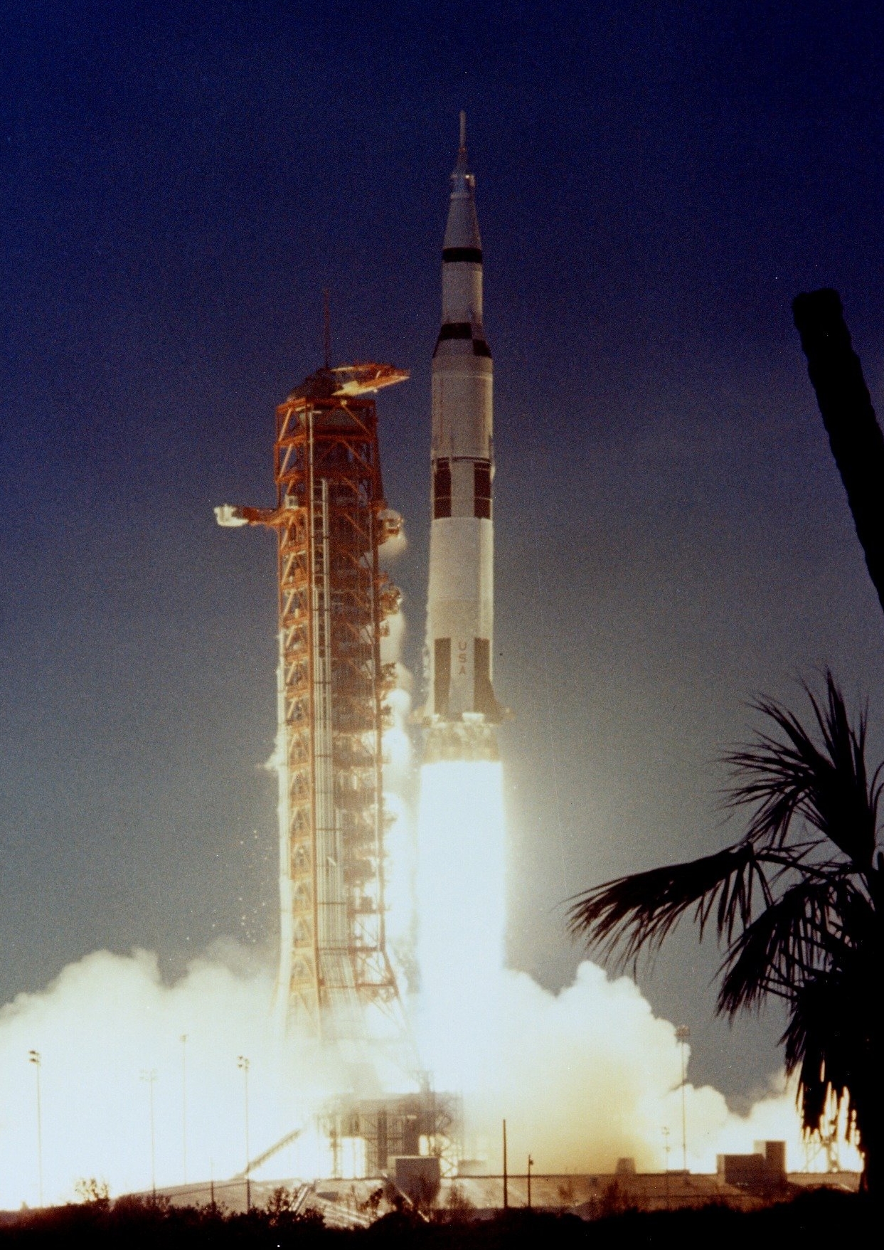
America's 2nd "Return to Space," January 31, 1971
Apollo 14, with Alan Shepard, Edgar Mitchell & Stu Roosa onboard, departs Kennedy Space Center for the Moon  nine months after the nearly-disastrous Apollo 13 mission. For Admiral Shepard, America's first astronaut, it had been a longer wait. 10 years had passed since that first 15 minute suborbital flight of the Mercury program. After being grounded for an inner ear condition, now in command of only his second (and last) spaceflight, Apollo 14 would become the only flight to the Moon made by any of the "Original Seven." [NASA/ASJ].

IAU names craters to honor Columbia crew

Columbia crater group, Apollo basin (Chang'e-2)
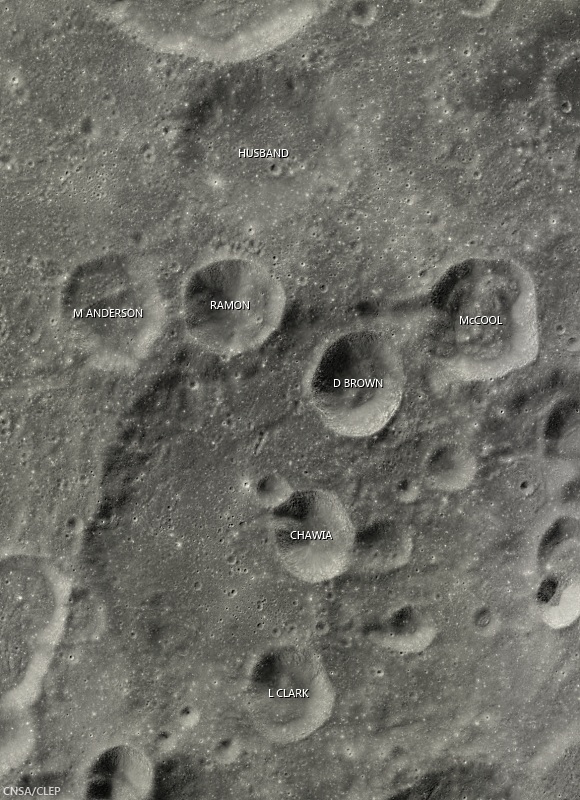
Craters in this grouping on the southeast side of the ancient Apollo basin have been preliminarily named in honor of the crew members of Space Shuttle Columbia, who perished during re-entry February 1, 2003.  Though some in the group seem to be large secondary craters from the same event Husband, formerly Borman L, is older than the others  Field of view from Chang'e-2 global high-Sun mosaic [CAS/CNSA/CLEP].
Keith Cowing, at the Lunar Orbiter Image Recovery Program (LOIRP) website "Moonviews" reports a crater grouping in Apollo basin (35.7°S, 208.0°E) has been provisionally designated by the International Astronomical Union to honor of each of the seven astronauts who died in the catastrophic failure of Space Shuttle Columbia February 1, 2003.

Columbia group, Apollo basin
Columbia crater group, in context with Apollo basin and craters there named after the Space Shuttle Challenger group, among others. The larger crater at center left, named in honor of Apollo 1 crew member Roger Chafee, is roughly 50 km across  [NASA/USGS/ASU].
Columbia crater group, lunar farside (LROC WAC DTM)
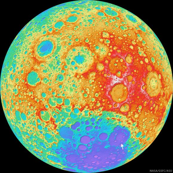
Locating the Columbia crater group (arrow) in Apollo basin, itself nested near the edge of the South Pole-Aitken basin, on an orthographic projection of the lunar farside. False color elevation map from LROC Wide Angle Camera digital terrain model (WAC DTM) [NASA/GSFC/ASU].

Saturday, January 29, 2011

New Robotic Lander Prototype skates tests


The Robotic Lander Prototype produced at Marshall Space Flight Center, on modified skateboards and a customized track system (a low-cost solution to control movement during final testing of the prototype’s sensors, on-board computer and thrusters [NASA/TBE].
Kim Newton
Marshall Space Flight Center

NASA engineers successfully integrated and completed system testing on a new robotic lander recently at Teledyne Brown Engineering’s facility in Huntsville in support of the Robotic Lunar Lander Project at NASA's Marshall Space Flight Center in Huntsville, Alabama.

The lander prototype was placed on modified skateboards and a customized track system as a low-cost solution to control movement during final testing of the prototype’s sensors, onboard computer, and thrusters. The functional test focused on ensuring that all system components work seamlessly to sense, communicate, and command the lander's movements.

The prototype will be transported to the United States Army Redstone Arsenal Test Center in Huntsville this week to begin strap-down testing, which will lead to free-flying tests later this year.

The lander prototype will aid NASA’s development of a new generation of small, smart, versatile landers for airless bodies such as the moon and asteroids. The lander's design is based on cutting-edge technology, which allows precision landing in high-risk, but high-priority areas, enabling NASA to achieve scientific and exploration goals in previously unexplored locations.

Development of the lander prototype is a cooperative endeavor led by the Robotic Lunar Lander Development Project at the Marshall Center, Johns Hopkins Applied Physics Laboratory of Laurel, Maryland and the Von Braun Center for Science and Innovation, which includes the Science Applications International Corporation, Dynetics Corporation, Teledyne Brown Engineering, Inc. and Millennium Engineering and Integration Company, all of Huntsville.

For more information on the Robotic Lunar Lander Development Project, please visit http://www.nasa.gov/roboticlander.

Friday, January 28, 2011

The Challenger Crater Group of Apollo Basin


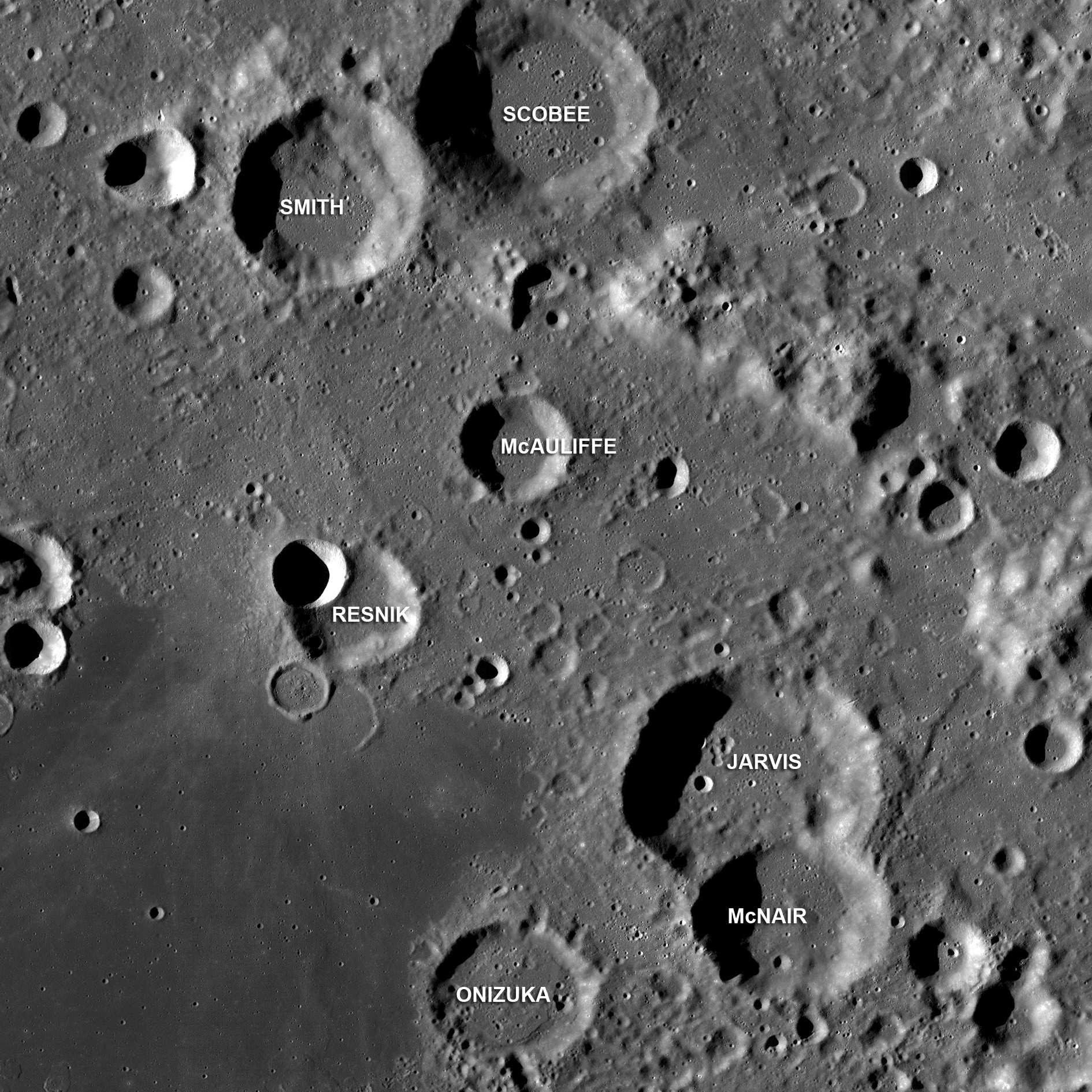
The Challenger Crater Group in Apollo Basin, on the Moon's farside (36°S, 209°E); LROC Wide Angle Camera monochrome (643nm) mosaic from a series of passes stitched around M118491411ME, gathered over the course of three orbits January 18, 2010. The crater group is named for the crew of the Space Shuttle Challenger killed when America's second orbiter was destroyed by an external tank explosion 73 seconds after launch from Kennedy Space Center, January 28, 1986. Craters elsewhere in the basin were also officially designated to memorialize the crew of Apollo 1 and Columbia [NASA/GSFC/Arizona State University].
Mark Robinson
Principal Investigator
Lunar Reconnaissance Orbiter Camera
Arizona State University


Apollo is a 524 km-diameter impact basin located within the center of the the giant South Pole-Aitken basin. Apollo is also a Constellation Project Region of Interest, identified by NASA as a notional area for future human lunar exploration. The Constellation ROI is located in the southwest corner of the mare deposit that fills this basin-within-a-basin.
After the loss of the Space Shuttle Challenger these seven craters on the eastern rim of Apollo were named after Greg Jarvis, Christa McAuliffe, Ron McNair, Ellison Onizuka, Judy Resnik, Dick Scobee and Mike Smith.

View the WAC mosaic of the entire Apollo basin and surroundings.

Visit NASA's Day of Remembrance webpage, HERE.

NASA Lunar Science Forum IV


FIRST ANNOUNCEMENT:

Clive R. Neal
University of Notre Dame

The NASA Lunar Science Institute is pleased to announce the 4th annual NASA Lunar Science Forum, to be held July 19-21, 2011.

This year's forum will feature sessions on recent scientific results from the Lunar Reconnaissance Orbiter (LRO) and Lunar Crater Observation and Sensing Satellite (LCROSS), dedicated side-conferences for graduate students and young lunar professionals, as well as the annual recognition of scientific accomplishments and associated keynote lecture.

As in past years, science sessions are structured to report on both recent results and future opportunities for lunar science, exploration, education and outreach.

We also look forward to news on the upcoming lunar missions GRAIL and LADEE and welcome abstracts across the many fields of lunar science.

Abstracts will be accepted starting February 21 through May 2, 2011 at http://lunarscience.nasa.gov/lsf2011

February's announcement will discuss the Lunar Science Forum logistics, but please save the date now as you make your summer meeting plans.

We look forward to another exciting meeting focusing on science Of, On and From the Moon!

Note: The 4th Annual NLSI Conference will be held once again this year at the NLSI's host facility, NASA's Ames Research Center at Moffett Field, California.

Rille in Aitken Crater


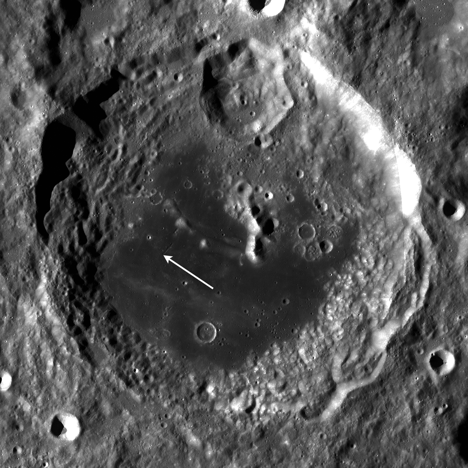
The beginning (or end) of a short rille within Aitken crater. The rille is 5 kilometers long and 600 meters wide. LROC Narrow Angle Camera observation M149391207, LRO orbit 7148, January 11, 2011; resolution 90 cm per pixel [NASA/GSFC/Arizona State University].

Drew Enns
LROC News System

Rilles can be formed by two basic processes: tectonism producing a graben due to faults running beneath the surface or volcanism carving long channels out of the surrounding terrain. Which process formed this rather short rille? The answer is likely volcanism. Two observations support this hypothesis. First the rille is located on a mare surface, itself created from volcanism, and second the rille is not straight, which can be seen in the WAC context image below. However, this does not rule out tectonism. Faulting can, and does, occur in volcanic plains, and faults are never perfectly linear. It's also possible that both forces helped shape the rille. We really don't know right now. The best way to find out would be to place astronauts in the area to conduct field studies. In the mean time scientists can use LROC and LOLA data to compare rilles across the Moon and better our understanding of rille formation.


Location of the linear rille, subject of LROC Featured Image January 27, 2011, within Aitken crater, LROC Wide Angle Camera monochrome mosaic [NASA/GSFC/Arizona State University].

Search for more interesting features in the NAC frame.

Related Posts
Terraced Craters in Aitken Crater
Exposed Boulders in the Aitken Mare

Exposed Boulders in the Aitken Mare


Boulders eroding out of the hillslope and concentrated between two hills. LROC Narrow Angle Camera observation M143480262, LRO orbit 6278, November 4, 2010. Featured Image width = 700 meters, resolution 70 cm per pixel [NASA/GSFC/Arizona State University].

Drew Enns
LROC News System

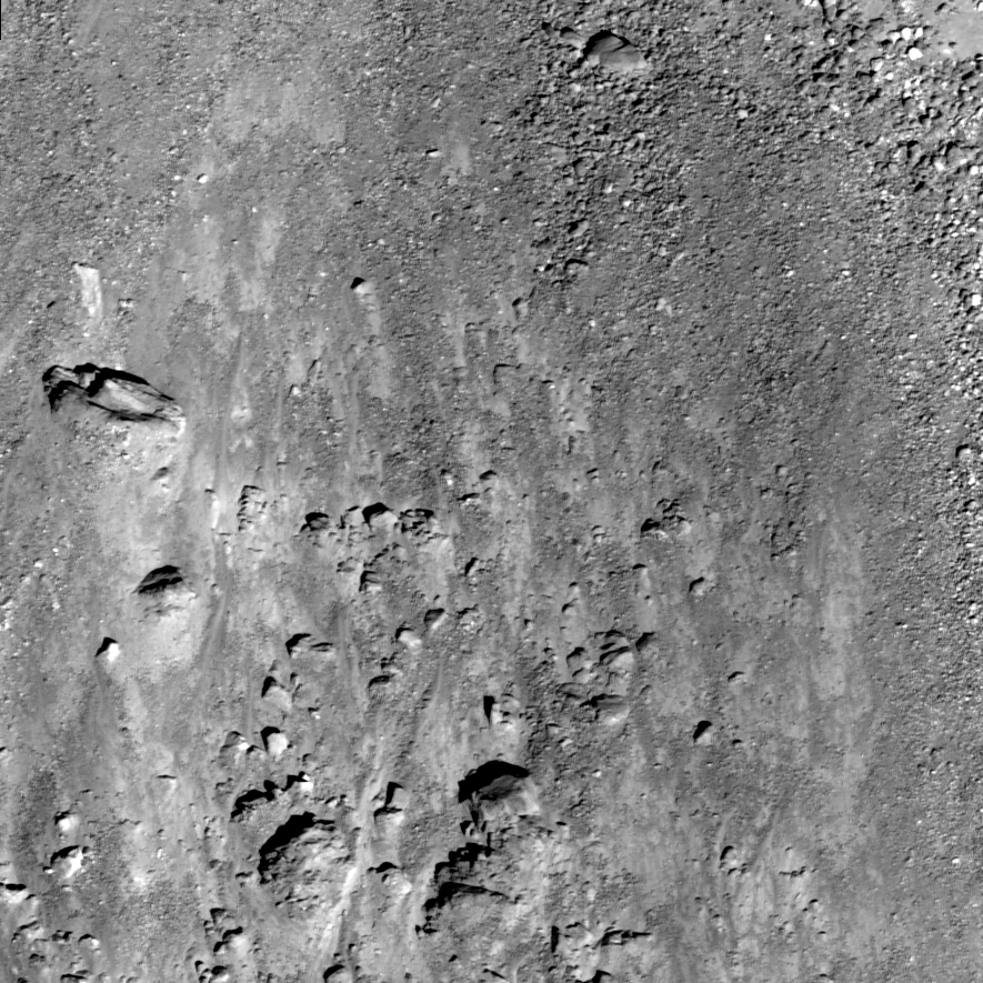
Boulder fields on the Moon are a fairly common feature. In general, large boulder fields are usually part of an ejecta deposit surrounding their parent crater or a product of gravity-driven mass wasting, where blocks on a slope are dislodged from the regolith or rock outcrops by various geologic processes (including meteorite impacts or moonquakes) and roll downhill. Since this boulder field is located at the base of a slope, it is likely a product of gravity-driven mass wasting. This field has boulders as large as 10 meters in size. Astronauts exploring Aitken crater could use boulder fields like this one, where materials from higher up have fallen to lower, more accessible elevations, to collect samples that otherwise would be very time-consuming to collect.


Location of the boulder field within Aitken crater. LROC Wide Angle Camera monochrome mosaic [NASA/GSFC/Arizona State University].

Can you find more boulders in the NAC image?

Related Posts:
Wrinkle Ridges in Aitken Crater
Terraced Craters in Aitken Crater
Gassendi's Fractures
Bouncing, Bounding Boulders

Tuesday, January 25, 2011

Terraced Craters in Aitken Crater


Small crater within Aitken has a terraced and hummocky floor with boulders strewn about and no bright rays (though when seen in context, below, is situated within a larger debris ray or area of anomalously optically immature regolith. LROC Narrow Angle Camera observation M145855135, LRO orbit 6628, December 1, 2010. Crater is roughly two kilometers wide [NASA/GSFC/Arizona State University].

Drew Enns
LROC News System

This crater has an unusual floor for its size. An impact crater of this size typically has a simple bowl shape, yet this example displays terraces and hummocks. The terraces give us insight into the impact material. A bolide that impacts a solid surface covered by loose material, for example mare covered by regolith, will use less of its energy to break up the loose material than solid material. The "excess" energy goes into excavating more material thus making for a larger diameter. Thus we see terrace at the boundary between the regolith and underlying more coherent material. The fact that the crater has no bright rays indicates that it is old - its rays have weathered into the background.


Location of the terraced crater (LROC Featured Image. January 25, 2011) within the landmark farside crater Aitken (16.8° S 173.4° E) [NASA/GSFC/Arizona State University].

Find more craters in the full NAC frame!

Related Posts:
Wrinkle Ridges in Aitken Crater
Aitken Central Peak, Seen Obliquely
Approaching Aitken Crater - Vertregt J

Saturday, January 22, 2011

Wrinkle Ridges in Aitken Crater


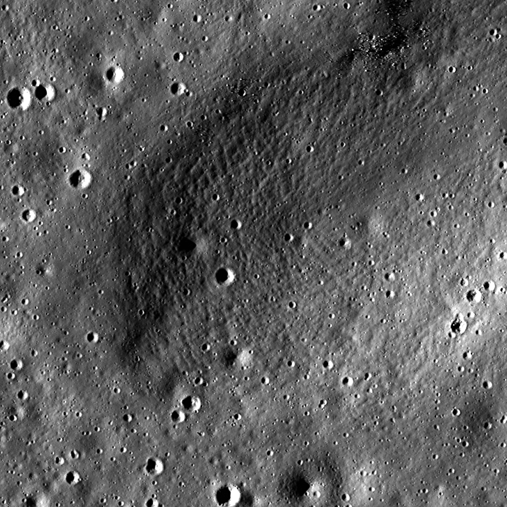
Mare basalts and hummocky ejecta both displaying wrinkle ridges in Aitken crater. LROC Narrow Angle Camera observation M105730242, LRO orbit 731, August 24, 2009; image field of view, ~1.6 kilometers, Sun is from east by northeast (upper left) [NASA/GSFC/Arizona State University].

Drew Enns
LROC News System

Aitken crater, located at 16.8° S 173.4° E, is a 135 km Upper Imbrian-aged crater. It is notable in that its floor is filled by a mare deposit, and that it, along with the Moon’s South Pole, is the namesake for the biggest and most ancient lunar basin, South Pole-Aitken Basin (SPA). Within its flooded floor are many scientifically interesting features, one of which are wrinkle ridges.


Location of wrinkle ridges within Aitken crater. LROC Wide Angle Camera mosaic displays an area 163 kilometers wide [NASA/GSFC/Arizona State University].

The dark mare basalts in the left half of the image were deformed by contractional forces into narrow, very sinuous (winding) landforms called wrinkle ridges. This pattern of deformation is not uncommon in mare basalts, and the small size of the ridges may indicate that the thickness of the volcanic fill in this area of Aitken crater is thin. The light (high albedo) material in the right half of the image is hummocky (hilly) impact ejecta. The same contractional forces that deformed the mare basalts into wrinkle ridges likely thrust up this ejecta forming analogous ridges. Wrinkle ridges are not often found outside of mare, something unusual is at work in Aitken crater! Note that the wrinkle ridge in the ejecta is more uniform in width and less sinuous than the wrinkle ridge in the mare basalt. This contrast in the two tectonic landforms may be an expression of a difference in the strength and other mechanical properties between the mare basalts and ejecta. The ejecta is most likely loose and unconsolidated, while the mare is more coherent. Thus when they are compressed they respond differently.

Search for more wrinkle ridges in the mare and highlands in the whole NAC mosaic.


A wider view of LROC NAC M105730242 and a closer view of the slow shedding of boulders on top of a wrinkle ridge, part of the diverse morphology of Aitken's interior [NASA/GSFC/Arizona State University].

Related Posts:
Aitken's Central Peak, Seen Obliquely.

Thursday, January 20, 2011

Vertregt J: Approaching Aitken


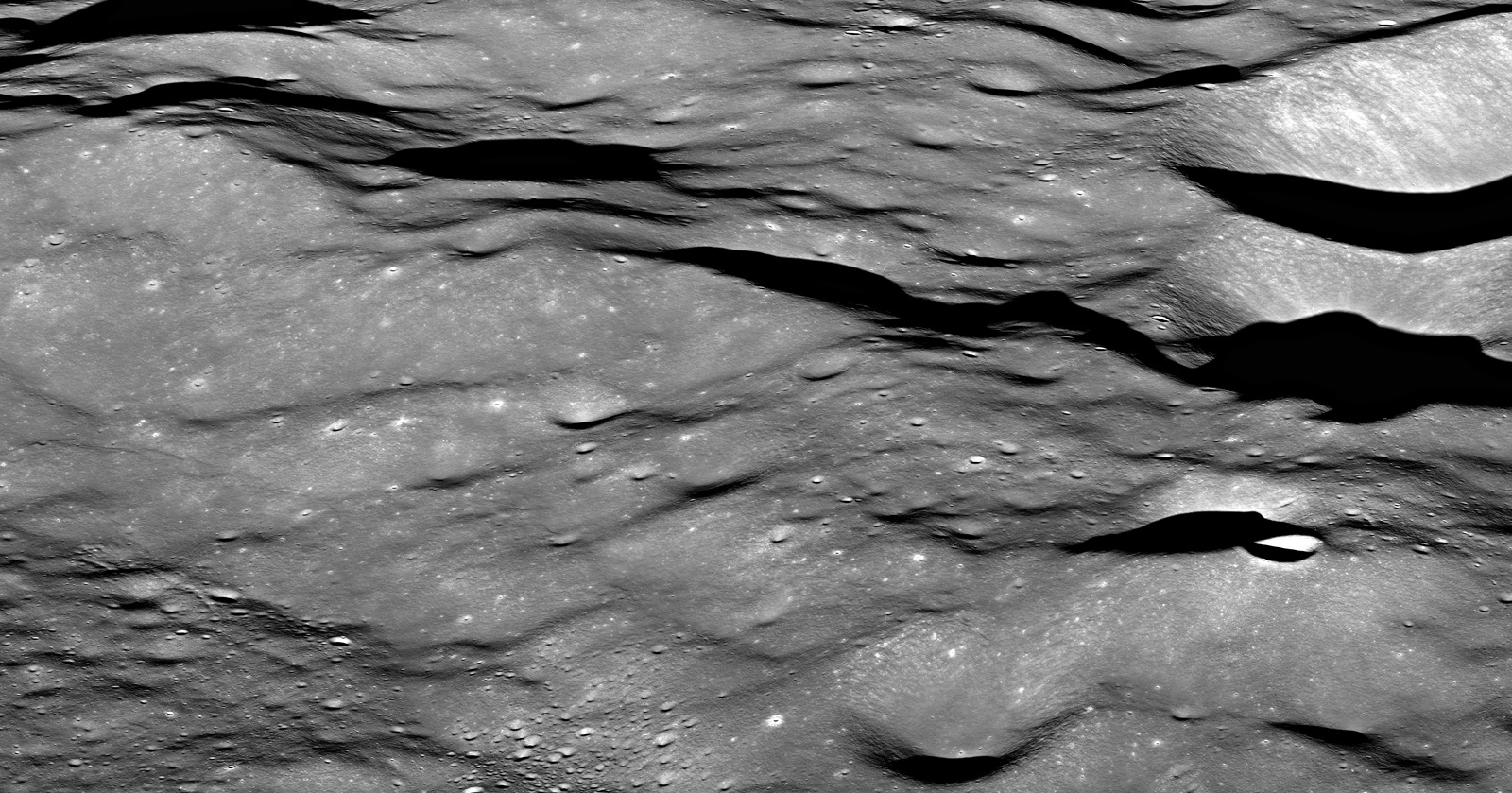
During orbit 7152, January 11, 2011, as LRO slewed to obliquely view Aitken crater (Featured Image, January 17), the northern edge of Vertregt J was serendipitously captured by the Narrow Angle Camera. North is to the left and the image field of view is about 6 kilometers [NASA/GSFC/Arizona State University].

Mark Robinson
Principal Investigator
Lunar Reconnaissance Orbiter Camera
Arizona State University


Extreme oblique views are a luxury with the LRO mission, since most instruments (including LROC) need to be pointed nadir (straight down) most of the time. Also, thermal concerns limit when LRO can look off to the side. The LROC targeting team closely monitors when opportunities arise to target extreme slews and acquire spectacular views (Bhabha crater).


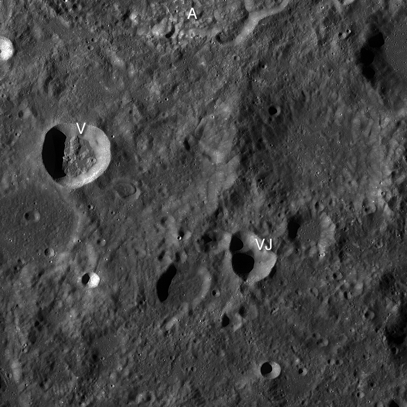
LROC Wide Angle Camera mosaic, centered on the Vertreg J (21.5°S, 174.3°E) oblique NAC featured image, January 19, 2011. Image field of view is 80 kilometers; A = bottom of Aitken crater, V = Vertregt K & VJ = Vertregt J [NASA/GSFC/Arizona State University].

Sometimes LROC obtains images while the spacecraft is slewing to a steady off-nadir position, which takes about ten minutes, in order to acquire oblique views. When possible the LROC targeting team will squeeze in a short NAC image just as the spacecraft is nearing the slew position - when this type of targeting works we sometimes obtain spectacular views such as today's featured image.


The full Narrow Angle Camera oblique view, with the double crater Vertregt J partially seen in the southeast background (right). The full scene is about 30 kilometers wide, LROC NAC M149411489 [NASA/GSFC/Arizona State University].

The region around Vertregt J (21.46°S, 174.32°E) is typical of the highlands - hilly and rugged. About seventy percent of the Moon is mapped as highlands, yet this most common terrain type is only poorly sampled. Only one Apollo mission explored a true highland target: Apollo 16.

As it turns out, results from the Clementine and Lunar Prospector missions showed lunar scientists that the chemistry of Apollo 16 rocks differs significantly from most the highlands. Murphy's law at work!

Lunar scientists need samples from other highland targets, especially inside the South Pole Aitken Basin (SPA) basin, to get a better handle on the origin of the lunar crust and the history of asteroid bombardment early in our solar system's history.

Explore at full resolution the Vertregt J oblique view.

Also visit the oblique view taken a few minutes later across the center of Aitken crater.

Explanation of "lettered craters" on the Moon.

Tuesday, January 18, 2011

Oblique view of Aitken's central peak


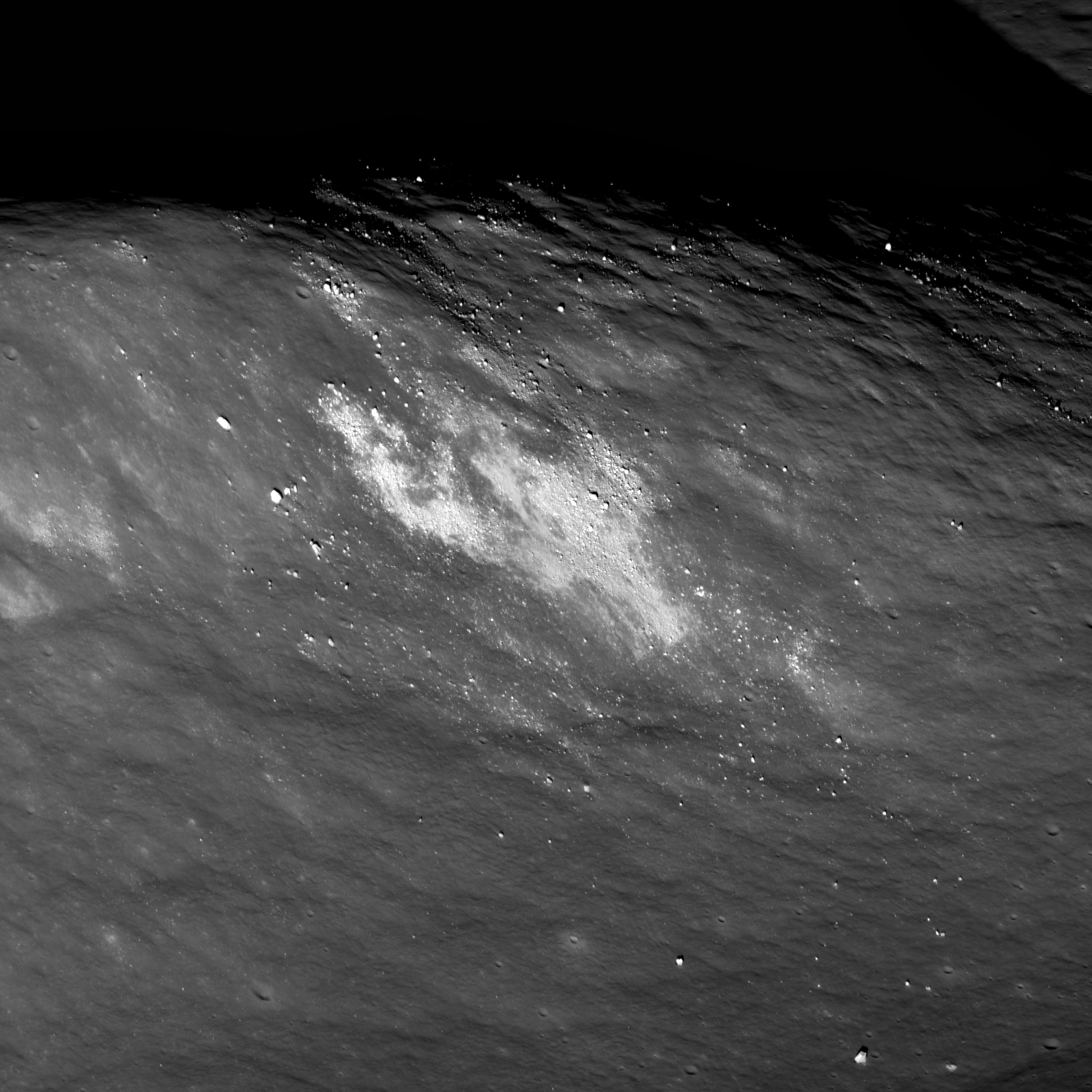
Southern end of Aitken crater central peak complex. The upper left is about 1000 meters above the crater floor, which is just seen at lower right. Bright material (high albedo) may be a landslide of local soil, or a secondary impact from a small nearby impact crater. Distance along ridge line is ~4 km [NASA/GSFC/Arizona State University].

Mark Robinson
Principal Investigator
Lunar Reconaissance Orbiter Camera
Arizona State University


Occasionally LRO is commanded to look off to the side at extreme angles to snap spectacular views. On 11 January, 2011 (hot off the press!) LROC shuttered this spectacular of Aitken crater. Here LROC was looking over the southwest ridge of its central peak. In the distance the lower portion of the northeastern walls of Aitken crater itself is just visible. In the center of the image is the Aitken crater Constellation Region of Interest.


LROC NAC oblique view of Aitken crater, including the central peak, northern walls, and the Constellation Region of Interest. Scene is about 30 km wide [NASA/GSFC/Arizona State University].

The Lunar Reconnaissance Orbiter has collected an extremely limited number of these oblique views of the lunar surface, which are useful for engineering purposes and visualizing key geologic features on the lunar surface -- like Aitken. Aitken (~135 km in diameter) is one of the most geologically diverse settings on the farside. The crater is mapped as an Imbrian-aged feature, and its floor is covered in a small puddle of mare basalt; mare deposits are quite rare on the lunar farside, and lunar scientists are still trying to figure out why. Aitken is also on the northern rim of the great South Pole-Aitken basin, the oldest and largest impact basin on the Moon and one of the oldest and largest impact basins in the whole Solar System! Further exploration of the South Pole-Aitken basin is one of the highest priorities for planetary science in the next decade.


LROC WAC mosaic of the central portion of Aitken crater. The arrow indicates a high albedo patch seen in the opening image [NASA/GSFC/Arizona State University].

This latest LROC oblique view gives you a sense of what astronauts will see on their terminal descent into Aitken. Check out the stunning full-resolution image and think about where you would go inside this spectacular geologic feature!

Read some of our previous postings about Aitken crater here, here, and here! And visit the central peak of Bhabha crater.

Friday, January 14, 2011

HEFT, Lies and Videotape


Cost and Schedule of Shuttle sidemount compared with HEFT alternatives. This is the only HLV option that meets all legal requirements and fits within the budget and schedule assumptions of HEFT. Data derived from SSP Study NSTS 60583, dated June 8, 2010.

Paul D. Spudis
The Once & Future Moon
Smithsonian Air & Space

A real comedy of errors and misunderstandings collided this week between the new NASA Authorization Act of 2010 and the agency’s Human Exploration Framework Team (HEFT) Congressionally mandated 90-day report (their initial findings on how to implement agency direction). Thought flush with the usual beautiful graphics and platitudes, the report’s bottom line is that under the existing budget and schedule, the agency cannot make the new heavy lift launch vehicle specified in the new authorization bill. In other words, you can’t get there from here. Can’t be done. Period.

Reading through the new report is an exercise in déjà vu for space policy geeks. It reads very much like the Exploration Systems Architecture Study (ESAS) of 2005. No big surprise, when one realizes that many of the people who wrote that report are involved in the new one. But more than that, the sense of a previous life stems from the rocket design that has resulted from this effort. It looks remarkably similar to the rocket that resulted from the previous effort, the late and not-so-lamented Ares family of heavy lifters. As you may recall, a key conclusion of the oft-cited Augustine Committee report was that the existing program of record (Project Constellation, a.k.a. Ares rocket) was unaffordable without infusions of significant quantities of new money.

Did NASA get a big infusion of cash? No. So no one should be surprised that the same people, working under the same assumptions within the same agency and technology base as the Project Constellation people would reach the same conclusions. In fact, most were not surprised. But apparently, many in the United States Senate did expect a different answer. Or did they?

We now enter the political Hall of Mirrors in which what people say they want isn’t necessarily related to what they really want or don’t want. Let us see if we can chart a path through the maze of motives, desires and statements to fully understand exactly what’s going on. Please stay with me on this until the end; I will try to make things clear.

Seven years ago, we had the Vision for Space Exploration (VSE), a statement of strategic direction in space. The VSE called for returning Shuttle to flight after the Columbia accident, completing construction of the ISS, the building of a new space transportation system, a return to the Moon (“with the goal of living and working there for increasing periods of time”) and finally, human missions to Mars and “other destinations.” After the VSE was announced, NASA “implemented” it by completing steps 1 and 2. Step 3 was started, outlining an architecture and design for a new human spacecraft and new launch vehicles (the ESAS). We never progressed beyond that, although many departments, universities and international partners dug in and began conducting studies of work and instruments needed to live on the Moon.

It is a fool’s errand to design architectures and new space vehicles if you do not know what your mission is. You can design and build a space system without an objective but as it must satisfy many different purposes, it tends to not satisfy any of them particularly well. From the beginning, NASA leadership didn’t acquaint itself with why they were tasked with lunar return, even though the VSE founding documents are quite clear on the purpose and activities associated with lunar return. Because of this strategic confusion, it was largely assumed by many that we would do on the Moon what we did 40 years ago – explore, collect samples, and leave as soon as possible (that last activity being particularly favored within the agency). To accommodate this activity, the Ares launch vehicles were designed to conduct a lunar mission with two launches – the Ares I, which would put the crew vehicle in low Earth orbit and the Ares V, which carried all the other pieces. Additionally, NASA never lost sight of its desire for Mars, so Ares V was sized at a payload capacity of 160 tons, overkill for a lunar mission but thought to be the right number for a human Mars mission, staged completely from the surface of the Earth (whether that’s true is another story).

As Ares rocket development costs rose, other pieces of the lunar return architecture were discarded. Eventually, we had a large rocket-building program but its purpose had become diffuse and nebulous (in 2009, the acting Administrator of NASA told Congress in testimony that he did not know what going to the Moon meant).

Curiously, the new NASA Authorization Act of 2010 was remarkably specific about the requirements of a new heavy lift vehicle the agency had been directed to build. It was to use Shuttle hardware to “the extent practicable” and initially carry 70-100 tons but designed such that it could be stretched to a lift capacity of 130 tons. Where did these numbers come from? It’s not clear, but here’s an interesting coincidence: 130 tons was the lift the capacity of the old Saturn V (118,000 kg = 260,000 pounds = 130 tons). NASA has interpreted the new Congressional language as meaning metric tons (2200 lbs) but the simple language of the law says “tons” (1 ton = 2000 lbs). One might suspect that the calculus was that heavy lift in days of old (Saturn V) meant 130 tons, so that’s what “heavy lift” should be.

In the absence of any specific mission, the payload capacity of your launch vehicle is entirely academic. But this “requirement” has had some serious ramifications. Last summer, a study group at Johnson Space Center released a report (Preliminary Report Regarding NASA’s Space Launch System and Multi-Purpose Crew Vehicle, Pursuant to Section 309 of the NASA Authorization Act of 2010 (P.L. 111-267), SSP Study NSTS 60583, dated June 8, 2010) showing how a heavy lift vehicle could be built and flown under the then-current run out budget (any new budget for NASA is pure guesswork at this stage). It resurrects an old concept of replacing the Shuttle orbiter on the existing stack with a payload fairing and engine pod. This configuration, called Shuttle Side-Mount (updated from the old “Shuttle-C” concept) was not considered by the HEFT study team, but meets the specific language of the new authorization. The advantage of SSM is that, as it is a minimal modification of the existing stack, it uses all of NASA’s existing launch and processing infrastructure – launch pads, mobile crawlers, scaffolding in the VAB and fabrication facilities in Michoud and Utah. SSM initially carries about 80 metric tons (70 (63.3 metric) to 100 (90.7 metric) tons) and can be stretched to meet the 130 ton (118 metric tons) legal requirement with minimal modification (for example, adding 5-segment (instead of 4-segment) Solid Rocket Boosters, 4 Shuttle Main Engines, extended External Tank). So in fact, SSM meets all the technical, budgetary, safety and schedule requirements set out in the NASA Authorization Act of 2010.

So as Oliver Hardy would say, here’s another fine mess we’ve gotten ourselves into. NASA creates an unaffordable architecture (ESAS) to implement the VSE. The response by the new administration is to cancel the VSE and replace it with promises of more distant goals at some nebulous time in the far future. Congress directs the agency to build an HLV anyway, but the vehicle has no mission, so they pull out the specs of the last HLV America flew. NASA responds by saying they can’t do it on the money and schedule specified, even though they themselves have in hand a report that shows how it can be done. Moreover, the agency still claims it doesn’t know why anyone would want to go to the Moon, despite having been shown repeatedly that what we do there will create new space faring capability.

You just gotta love this business.

Tuesday, January 11, 2011

Moon Flower


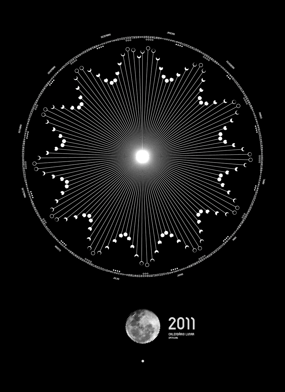
Moon Flower – Dimitre Lima creates a beautiful poster of lunar cycles, shaping them organically and a silver-on-silkscreen finish.

Saturday, January 8, 2011

Rep. Giffords critically injured in shooting


U.S. Rep. Gabrielle Giffords (D-AZ), wife of astronaut Mike Kelly and mother of two, is sworn into the 112th Congress, Wednesday, by newly-elected Speaker of the House John Boehner (R-OH). Rep. Giffords was shot point blank during a public event in Tucson Arizona and critically injured, Saturday January 8. Just out of extensive neurosurgery, her prognosis is "optimistic." Eighteen people were injured in the attack. Among those confirmed dead is a nine-year-old girl and federal Judge John M. Roll.

Jared Loughner (b. 1988) has been arrested in connection with the shooting.

Irresponsible rumors, including deliberate disinformation, about possible political motives for the shooting are flying back and forth, but one friend and fellow "former band member" Caitie Parker of Ohio Valley in Arizona describes the alleged shooter as "reclusive" since alcohol poisoning in 2007.

She described his politics as "definitely left wing," though most sources demonstrate the assailant to be mentally ill.

Thursday, January 6, 2011

Regolith: The "Other" Lunar Resource


The Pantheon of Rome, a 2000-year old concrete structure.

Paul D. Spudis

The Once & Future Moon
Smithsonian Air & Space

In civil engineering, one of the most important material resources on Earth is “construction aggregate” – the sand, gravel and cement building materials that make up the infrastructure of modern industrial life. Aggregate is easily one of the biggest, most valuable economic resources of all mined terrestrial materials – more so than gold, diamonds, or platinum. We depend on aggregates for many different types of objects; they are the fundamental building block of roads and structures. The use of aggregates in building goes back to ancient civilizations; concrete was used in buildings of ancient Egypt. The Romans devised a recipe for a concrete so durable that the molded arches, walls and self-supporting dome of the Pantheon (made over 2000 years ago) stand today. Aggregates in terrestrial use typically depend on a lime-based cement that bonds the particulate material together. Both lime (CaO) and abundant water are needed to make concrete on Earth.

On this blog and elsewhere I have detailed the importance and significance of water at the poles of the Moon. Water is indeed the most important early product to produce from lunar materials but there are other resources on the Moon. A permanent presence on the Moon will require infrastructure that must by necessity use as much local material as possible. Aggregate materials probably will become the primary building blocks of industrial society off planet, just as it has on the Earth. The composition and conditions of local materials will require some adjustments as to how we use lunar aggregate. A little thought reveals some interesting parallels and differences with terrestrial use.

On Earth, gravel pits are carefully located to take advantage of the sorting and layering produced by natural fluvial (river water-eroded) activity. We harvest gravels from alluvial plains and old river beds, where running water has concentrated rocks, sand and silt into deposits that can be easily excavated, loaded, and transported to sites of construction. The highly variable currents, as well as the velocities of flow of our terrestrial streams and rivers, sort the aggregate by size, creating layers of gravel-sized up to cobble-sized stones for the fastest flowing waters. Finer grained material is likewise concentrated where water speeds are low and sand and silt settles out from the suspended sediment (the “bed load”).

No natural process on the Moon creates such deposits, but the lunar surface rock has already been disaggregated by impact into a chaotic upper surface layer called regolith. Regolith is basically ground-up bedrock; impacts of all sizes constantly pummel the surface, breaking, fracturing and grinding up the Moon’s bedrock. Impact both breaks up and creates rock. An impact will destroy a rock both by shock (catastrophic rupture) and through cratering (fragmentation and excavation). The effect of such destruction is to make “soil,” fine-grained rocky material made up of the mineral grains of the bedrock. But impact also creates heat and this heat can weld small fragments into glass-rich aggregate rocks (regolith breccias) as well as quickly cooled fragments of melt that contain mineral inclusions (agglutinates, or glass). In broad terms, impacts destroy and disaggregate more than they create and weld together. Thus, on a given surface, regolith thickness increases with time – older surfaces have thicker regoliths.

The ground up regolith is a readily available building material for construction on the lunar surface. It is an aggregate in the same sense as on Earth, but with some significant differences. We could make lime and water from the surface materials of the Moon but it is very time and energy intensive. Thus, we must adapt and modify terrestrial practice to take advantage of the unique nature of lunar materials. The fractal grain size in the regolith means that we can obtain any specific size fraction we want through mechanical sorting (raking and sieving). Instead of water-set lime-based cement, we can use glass to cement particulate material together. Regolith can be sintered into bricks and blocks, as well as roads and landing pads, using thermal energy (passive solar, concentrated by focusing mirrors) or microwaves that can melt grain edges into a hard, durable ceramic.

The use of aggregate materials on the Moon will likely be gradual and incremental. Our initial presence on the Moon will be supported almost entirely by materials and supplies brought from Earth. As we gain facility using lunar resources, we can incorporate more and more local materials into structures. Simple, unmodified bulk soil is an early useful product. It can be used to build berms to protect an outpost from the rocket blast of arriving or departing spacecraft and to cover surface assets for thermal and radiation protection. The next phase will be to pave roads and pads to keep down randomly thrown dust and provide good traction for the multitude of wheeled vehicles supporting the outpost. Fabrication of bricks from regolith will allow us to construct large buildings, initially consisting of open, unpressurized workspaces and garages but ultimately, habitats and laboratories. Making glass by melting regolith can produce building materials of extreme strength and durability; anhydrous glass made from lunar soil is stronger than alloy steel with a fraction of its mass.

Eventually, we may be able to export these lunar building materials into space. A major drawback is the gravity well of the Moon – its escape velocity is about 2.38 km/s, smaller than that of the Earth but substantial. To use large quantities of lunar materials for space construction, we need to develop an inexpensive means to get material off its surface. Fortunately, the small size and no atmosphere of the Moon make this possible by literally throwing stuff off the Moon into space. A “mass driver” can launch objects off the lunar surface by accelerating them along a rail track using electromagnetic coils that hurl capsulated material into space at specific velocities and directions. We can collect such thrown material at a convenient location, such as one of the libration points. From there, it is a relatively simple matter to send the material to wherever it is needed in cislunar space.

Water remains the most important first lunar product, but the “other” lunar material regolith is almost as important. Lunar rock and soil will be the paving stones of the Solar System. As once all roads led to Rome, all new roads in cislunar space lead to – and from – the Moon.

Monday, January 3, 2011

Quanrantid stream followed by partial eclipse

From 41st Lunar & Planetary Science Conference (2010)

After the meteor shower, observers in Europe, northern Africa, the Middle East and parts of Asia can witness a partial eclipse of the sun.

In western Europe, as much as 86% of the solar disk will be covered by the Moon at dawn, producing a fantastic crescent sunrise on Jan. 4th. Follow the links for a live webcast, an animated map, and details from NASA

Read the story at SpaceWeather.com