Wednesday, February 9, 2011

LROC: Rupes Recta


Artful Lunar Picture of the Day (LPOD) contributor Maurice Collins of New Zealand created this mosaic of LROC Wide Angle Camera images, swept up at local sunrise, and demonstrates why Rupes Recta is easier to spot when the Moon is just past First Quarter as seen from Earth. The change in elevation is not unusually high, for the Moon, but the rift is consistent (even if segmented) throughout its more than 100 kilometer length. The Straight Wall is consistent with a change in topography, if not age and stratigraphy, dividing an eastern zone from a western slope, both within an inundated crater broken in half by the weight of later melt pressing down on the interior of Mare Nubium. This gentle rift casts a long shadow at sunrise, however, one that gradually thins until the Moon waxes Full, and afterward it stays visible in modest telescopes [NASA/GSFC/Arizona State University/MoonScience].

EDITOR'S NOTE: Every 90 days, each time Dr. Mark Robinson's Lunar Reconnaissance Orbiter Camera (LROC) team at Arizona State University releases its latest voluminous batch of low-orbit lunar photography, one of several bench mark locations we immediately search for updates has been the familiar "Straight Wall," Rupes Recta. LROC Featured Image February 9, 2011 examines and better explains a feature discussed here in a post originally uploaded July 8, 2010.

For a review of our many posts (and images) featuring Rupes Recta, we recommend the reader take a side trip HERE, or simply examine the list of relevant Lunar Pioneer links below the list of LROC "Related Posts" below.

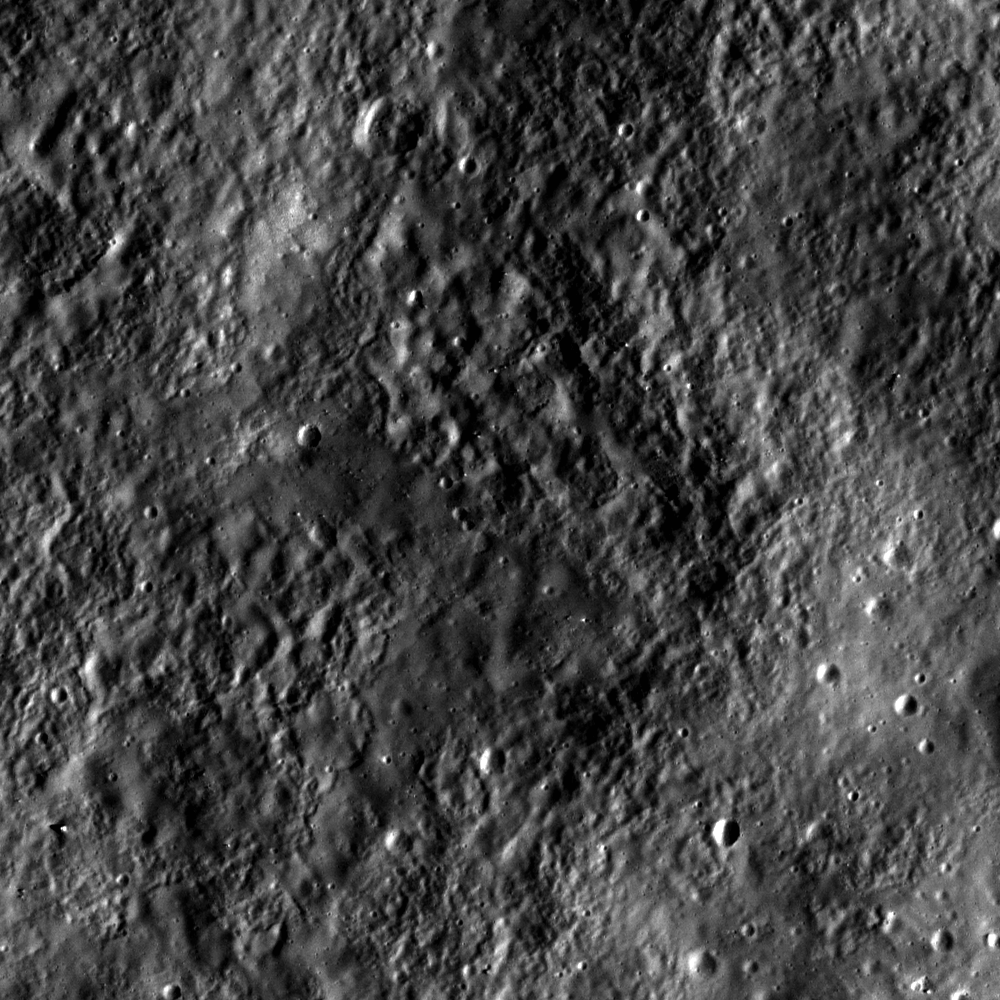
In July, when after we first began manipulating the same frame LROC released below, we described the image above as, a "closer look at the crater straddling the Straight Wall near 21.6°S, 352.2°E, The character of each half of the plain divided by the rift appears similar. Also, at this point in this montage, consisting of both the right and left frames of LROC Narrow Able Camera observation M122264663. For a Wallpaper-sized view of the above image, click HERE [NASA/GSFC/Arizona State University].


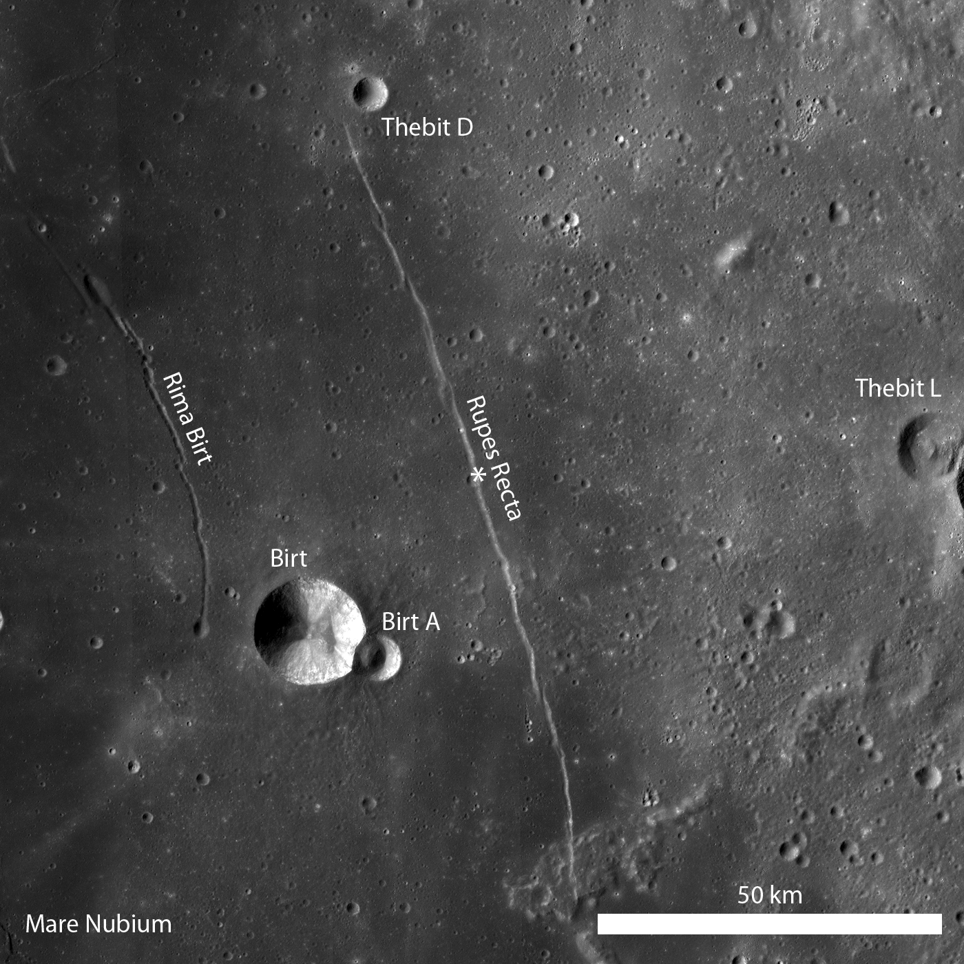
Rupes Recta is a well-known linear rille over 100 kilometers long, familiar in amateur telescopes, west of the central meridian in the Nearside southern hemisphere, seen here in an annotated portion of LROC Wide Angle Camera (WAC) monochrome mosaic; illumination from the west (left), the asterisk denotes the location where LROC Narrow Angle Camera (NAC) observation M122264663 intersected the fault, in the LROC Featured Image below [NASA/GSFC/Arizona State University].

Lillian Ostrach
LROC News System

Several weeks ago LROC featured a series of WAC monochrome mosaics of some of the most spectacular sinuous rilles on the Moon (Rimae Posidonius, Vallis Schröteri, and Rimae Prinz). Unlike sinuous rilles, linear rilles (or graben) are not believed to primarily result from lunar volcanism. Linear rilles are surface manifestations of structural faulting that formed when the lunar crust was pulled apart. The widths of these linear rilles range from as little as a few meters to kilometers across; Rupes Recta is between 1 - 3 km wide across its length. In addition, Rupes Recta is composed of several en echelon segments - the linear rille is not a single, uninterrupted 100 km length fault! There are at least 5 large fault segments visible at the LROC Wide Angle Camera scale (100 meters/pixel) ranging from around 8 to 50 kilometers in length.


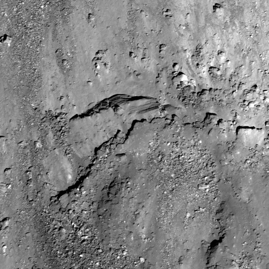
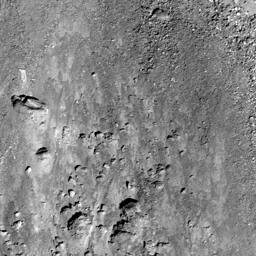
Cross-cutting relations between Rupes Recta and an impact crater are evident in this subset of LROC NAC observation M12264663R (LRO orbit 3151, March 3, 2010). The cliff-face of Rupes Recta is noted by the arrows on the right side of the image. At some point after the formation of Rupes Recta an impact occurred and excavated material from the fault wall. The arrows on the left side (forming a somewhat-curvilinear path) denote the crater wall. Subsequent down-slope movement of eroded debris and blocks is visible. Image field of view is 840 meters, illumination from the left, and a low-incidence angle highlights albedo variations [NASA/GSFC/Arizona State University].

What cross-cutting relationships can you determine in the LROC WAC monochrome mosaic? How does the full LROC NAC image change your view of Rupes Recta?

Related posts:
Linear Graben

Lunar Pioneer Posts:
A second NAC cross-section of Rupes Recta
More on that second Rupes Recta close-up
Rima Birt and Rupes Recta
LOLA/LROC: Hunting for ancient impact basins (LROC)
More Kaguya Terrain Camera images
Paul Spudis: Caves on the Moon
Google Moon, Limited (Part One)
A New Era of Lunar Exploration


Segment from the really outstanding LROC WAC monochrome mosaic of the >100 km-long segmented fault east of Mare Nubium in the Nearside southern hemisphere. The northern half of the feature is set apart here to note a cross-fault (upper arrow) first brought to our attention by Charles A. Wood in a discussion posted to his essential Lunar Picture of the Day (LPOD) website. The nearly perpendicular rille is often difficult to pick out in Earth-side photography but unmistakable in the LROC image. The lower arrow, again identifies the location of the impact crater in extreme close-ups above. The image field of view is approximately 40 kilometers [NASA/GSFC/Arizona State University].

Tuesday, February 8, 2011

Simulated view of the Tranquility Pit


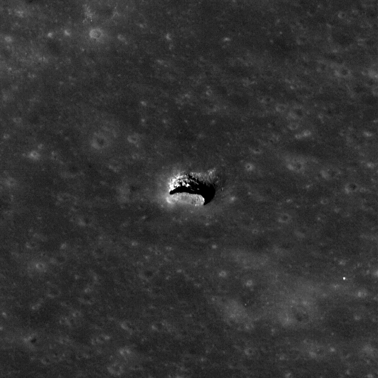
The second of four LROC Narrow Angle Camera (NAC) close-ups (M126710873R) of the estimated 100 meter-wide mouth of the cavern skylight in Mare Tranquillitatis (8.34°N, 33.22°E). The Sun was shining 63° above the east by southeastern horizon as LRO flew almost precisely overhead at an altitude of 40.57 kilometers, during orbit 3807, April 24, 2010. As follow-up observations accumulate tighter constraints on the dimensions of the "crater pit," one of only three discovered on the Moon since 2008, become possible [NASA/GSFC/Arizona State University].


Four months on, as the Moon continued to rotate eastward under LRO's polar orbit, the Tranquility Pit once again arrived in a favorable location for LROC observation, 45.41 kilometers under the opposite side of LRO orbit 5372. The encounter was not as precisely overhead as back in April, on August 24. LRO was commanded to slew some 7° off nadir while the Sun's illumination arrived on target from 52.62° over the west-southwest. This third of the four LROC NAC imaging opportunities revealed a different area of the cavern's interior and the eastern rough, bright wall of the skylight. (LROC NAC M137332905R [NASA/GSFC/Arizona State University].


This very rough juxtaposition of the two observations above allows a view of the cavern opening's anatomy otherwise impossible in an almost total absence of the kind of scattered light taken for granted on Earth [NASA/GSFC/Arizona State University].

Sublunarean Void


The LROC Narrow Angle Camera acquired an oblique view of the Marius Hills "Haruyama Skylight" pit at just the right angle to reveal an overhang. The pit is about 65 meters in diameter (LROC NAC observation M137929856R, LRO orbit 5460, August 31, 2010) [NASA/GSFC/Arizona State University].

Marc Robinson
Principal Investigator
Lunar Reconnaissance Orbiter Camera
Arizona State University


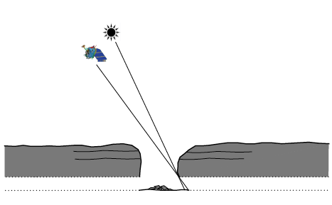
Since LRO completes a full cycle of lunar imaging each month, it is possible to follow up previous discoveries and re-image targets under different lighting conditions. The LROC team waited patiently until the Sun and orbit position in the Marius Hills region was such that the bottom of the previously imaged pit wall was illuminated at just the right angle so that if there was an open lava tube extending horizontally its floor would be illuminated. The spacecraft slewed 43° to the east and the solar incidence angle was 34° from vertical.


Schematic of the imaging geometry in cross section, allowing a view of the lava tube floor [Arizona State University].

In this geometry, the NAC was able to image a few meters under the overhang discovering a sublunarean void! Will astronauts someday explore under the mare? What scientific riches wait to be discovered within the unseen reaches of sublunarean voids?


LPSC XLII (2011) #2771, Figure 2b. "The Mare Tranquilitatis pit, imaged at LRO nadir (0.00°) (2a) and -51° (2b) slew angles; images; M126710873R and M144395745L, respectively. Note layering complexity, differentially modified pit wall profile, and funnel-shaped rim in 2b (red scale bars are ~ 100 meters along each length" [NASA/GSFC/Arizona State University].

Also note how the oblique angle really brings out the layered nature of the mare bedrock in the pit walls. These exposed layers give scientists important clues as to how the vast mare were deposited.

Explore the entire oblique image! Read the 2011 Lunar and Planetary Science Conference abstract describing details of this fascinating discovery.

Also check out previous Featured Images of the Mare Tranquillitatis and Mare Ingenii pits.

Monday, February 7, 2011

The Spectral Properties of Ina

Ahead of the 42nd Lunar & Planetary Science Conference, we highlighted selected presentations related to lunar science:

Ina, a unique 2.8 km-wide feature with a distinctly blue optical component originally spotted by Apollo astronauts from orbit. LROC Narrow Angle Camera observation M119815703, from 41.15 kilometers, orbit 2791, February 3, 2010; resolution 0.48 meters per pixel, incidence angle 56° [NASA/GSFC/Arizona State University].

THE SPECTRAL PROPERTIES OF INA: NEW OBSERVATIONS FROM THE MOON MINERALOGY MAPPER #2499.

Isaacson, Petro & Boardman et al
Planetary Science Institute, Brown University; NASA Goddard; AIG, LLC; U. Maryland; U. Tennessee

Introduction: The unusual morphology and appearance of Ina, originally referred to as ‘D-Caldera’ because of it’s unique shape (Figure 1), have been of interest to lunar scientists since it was first identified in Apollo images [1, 2]. Early studies of this 2.8 km wide depression interpreted it to be a lunar caldera or collapse pit, based in part on its location near the summit of a broad, low-relief dome [1-4]. The interior of Ina contains smooth mounds and small plateaus of positive relief surrounded by brighter and rougher, lower-lying floor materials [1-4]. Several lines of evidence suggest the presence of relatively fresh surfaces within the floor of the Ina depression [5,6]. These factors include the preservation state of small-scale relief, the small number of superposed craters and an apparent lack of significant space weathering associated with the bright interior regions. Based on these properties, portions of Ina’s interior have been interpreted as being less than 10 Myr old and perhaps still forming as the result of episodic outgassing from the deep interior of the Moon [6].

LPSC XLII (2011) Figure 1. Kaguya Terrain Camera morning image of Ina (light is from the east, mound features have positive relief).

Recent Narrow Angle Camera (NAC) images returned by the Lunar Reconnaissance Orbiter (LRO) are revealing the morphology of Ina at resolutions of up to 0.5 m/pixel [7]. While crater densities observed in this new data indicate an average age > 10 MY for the lower floor unit as a whole [7], the new data also show steep slopes and boulder fields down to the limit of resolution that may represent smaller areas of more recent disturbance. Reflectance data recently acquired by the Moon Mineralogy Mapper (M3) are assessed here to investigate the spectral properties and origin of these bright floor materials within Ina. M3 Data: The M3 imaging spectrometer was a guest instrument on India’s Chandrayaan-1 mission which launched on October 22, 2008 and mapped the lunar surface through August of 2009. M3 data of Ina and surrounding deposits were acquired twice in global mapping mode, which covered the wavelength range of ~430 to 3000 nm in 85 spectral bands. The first acquisition occurred in Optical Period 1b (OP 1b) at a spatial resolution of 140 m/ pixel and a phase angle of ~52 degrees. Preliminary M3 observations of Ina from this data acquisition are presented here. To provide an improved context for interpretation, M3 data have been co-aligned with Terrain Camera data from the Kaguya satellite (Figure 1) and topographic data acquired by the Lunar Orbiter Laser Altimeter (LOLA) aboard LRO.

LPSC XLII (2011) Figure 2. M3 mapper color composite (blue=460nm, green=1580nm, red=2780nm) overlaid on a Kaguya Terrain Camera image. Ina stands out from surrounding deposits due to its bright reflectance at blue wavelengths.

M3 Observations of Ina: Apollo 17 astronauts first observed the relatively blue color of the ‘rough, blocky’ floor materials in Ina that were described as having a ‘very light bluish-gray’ tint relative to surrounding materials, with raised bumps that were similar in color to surrounding terrain [8]. Figure 2 shows an M3 image of Ina in which these floor materials stand out relative to surrounding materials and the elevated interior mounds due to their bright reflectance in blue wavelengths of light (M3 460 nm band).

LPSC XLII (2011) Figure 3. Perspective view of Ina looking northwest, based on co-aligned 3M (Chandrayaan), Kaguya & LOLA (LRO) topographic data. Bright optically immature deposits on the floor of Ina appear green in this M3 color ratio composite due to a strong 1 micro-meter ferrous band relative to surrounding deposits (b=460/750nm, g=750/990, R=750/460nm) [NASA/JAXA/ISRO].

Figure 3 shows an example of a M3 ratio composite as a perspective view using LOLA topographic information. As in Figure 2, this image has been overlaid on Kaguya data to provide greater morphologic context for interpretation of the M3 reflectance data. This M3 data demonstrates that the strong ferrous absorption associated with relatively unweathered materials identified in previous studies [6] are related to bright floor materials within Ina, rather than broad topographic slopes. In contrast, the raised mounds within Ina lack a spectral signature associated with freshly exposed surfaces. Figure 4 compares floor materials within Ina displaying the strongest mafic bands to optically immature (‘fresh’) mare craters in Mare Serenitatis and Mare Tranquillitatis (low and high-titanium mare basalts, respectively). For these comparisons, the least weathered 1% of mare materials by surface area were sampled from each basalt type based models of mare maturity [9, 10]. The least-weathered floor materials within the Ina depression (average of eight 140m x140m pixels) are found to resemble very fresh materials within recent craters in Mare Tranquillitatis.

LPSC XLII (2011) Figure 4. A 3M reflectance spectrum of the brightest interior regions are compared to surrounding soils, as well as fresh mare craters in high and low titanium mare basalts.

Summary and Future Work: Preliminary examination of M3 data for the Ina structure is consistent with previous studies [6] that have identified relatively unweathered high-titanium basalts within the blocky floor materials. These results support the interpretation that floor materials within Ina have been disturbed recently enough to be spectrally similar to small, fresh mare craters within Tranquillitatis. Calibrations and analysis of the M3 Ina data are on-going and have yet to be fully corrected for thermal emission and scattered light. Future investigations will more fully explore these new data and associated lunar features for maturity and mineralogical information as well as the possible presence of volatile components. No significant signs of volatile components have been observed in preliminary analysis of these data.

References: [1] Whitaker, E. A. (1972), NASA SP-289, 25, 84-85, , [2] El-Baz, F and A. W. Warden (1972) NASA SP-289, 25, 1-25 [3] El-Baz, F. (1973) NASA SP-330, 30, 13-17. [4] Strain, P. and F. El-Baz (1980), PLPSC, 2437-2446. [5] Schultz, P.H. (1991), LPI Techn. Rept. 91-03, 37-38, [6] Schultz, P.H. et al. (2006), Nature, 444, 184-186. [7] Robinson, M. et al. (2010), LPSC 41, 2592 [8] Evans, R. E. and F. El-Baz (1972) NASA SP-289, 28,1-32. [9] Staid, M. and C. M. Pieters (2000), Icarus, 145, 122-139 [10] Wilcox et al. (2005), JGR, 110, E11001.
- 42nd Lunar and Planetary Science Conference (2011)

The LROC NAC frame at the beginning of this post superimposed on an LROC WAC monochrome mosaic that is, in turn, overlaid upon the lunar digital elevation model available to users of the Google Earth application (>v.5), looking northwest toward the eastern range of the Montes Apenninus more than 100 km away. This perspective is similar to that seen in Figure 3 -LPSC XLII (2003) #2499.

New dark-halo craters in Alphonsus

Over the coming weeks, in anticipation of the 42nd Lunar & Planetary Science Conference, we are again this year highlighting some of the announced presentations related to lunar science:


Familiar nearside landmark 121km Alphonsus, near 13.4°S, 357.2°E. LROC Wide Angle monochrome (643nm) mosaic composed from images swept up by the LROC Wide Angle Camera in four successive orbital flyovers on February 4, 2010. Most of what is known of small pyroclastic vents and their association with the dark mantling material surrounding them comes from study of this crater, well-placed for study from Earth on the Moon's central meridian. Recently analysis of recent high-resolution data has uncovered at least two previously unrecognized vents in the floor of Alphonsus [NASA/GSFC/Arizona State University].

ALPHONSUS DARK-HALO CRATERS: IDENTIFICATION OF ADDITIONAL VOLCANIC VENTS, #2691.

Gaddis, et al. Astrogeology Science Center, U. S. Geological Survey; Northern Arizona University; Cornell University; University of Hawaii;
Intergraph Corporation

Overview: Dark-halo craters located along fractures in the floor of Alphonsus crater (108 km dia.; ~13ºS/357ºE) are considered type localities of small lunar pyroclastic deposits based on association of dark mantling material with likely cone-shaped source vents. Much of our understanding of the physical processes involved in smaller pyroclastic eruptions on the Moon comes from morphometric analyses of deposit volumes in Alphonsus crater performed by Head and Wilson [1]. These authors used high-resolution photographs and topographic maps to map the distribution and measure volumes of materials in the pyroclastic cones. They identified juvenile materials in all but one of the “dark halo” crater deposits. This study presents evidence for at least two previously unrecognized vents in the floor of Alphonsus crater. Results suggest that many such features and associated pyroclastic deposits are likely to be identified with the wealth of new lunar remote sensing data [e.g., 2, 3, 4].

Geologic Setting: Alphonsus is a Lower Imbrian-age crater located in the highlands east of the Upper Imbrian-age Mare Nubium [5]. The crater has a ~flat, cratered floor, a central peak, and a broad rim (Figure 1). Numerous linear rilles dissect the crater floor and dark-halo craters are located along and adjacent to the rilles, suggesting that the fractures provided preferential pathways for dike emplacement, volatile accumulation and subsequent pyroclastic eruption. Eleven dark-halo craters were mapped previously within Alphonsus [1]; ten of these are located within 25 km of the basin rim. These dark halo craters are characterized by non-circular rims.


LPSC XLII (2011) 2691 Figure 1. Alphonsus crater and the locations of major floor fractures (green), Eleven dark-halo craters identified previously by Hawk & Wilson (1979) and two newly identified vents. Kaguya Terrain Camera evening mosaic [JAXA/SELENE].

Analysis: Because of their iron-rich compositions, the volcanic deposits within the floor of Alphonsus crater are highlighted as bright in FeO maps derived from Clementine UVVIS data [10]. Examination of these data (Figure 2) reveals obvious iron-rich materials in association with the 11 previously recognized vents, but at least two additional sites are also highlighted (arrows). To examine these sites in more detail, we used data from the Lunar Reconnaissance Orbiter (LROC) Narrow Angle Cameras (NAC) [2; ~0.5 m/p] and the JAXA SELENE/Kaguya Terrain Camera [3; ~10 m/p].


LPSC XLII (2011) 2691 Figure 2. Alphonsus crater viewed by Kaguya Terrain Camera evening mosaic with superimposed false-color Clementine derived iron-oxide (Lucey, et al., 2000). Yellow tones show enhanced iron content, arrows mark the sites of two possible newly identified pyroclastic deposits [JAXA/SELENE/NASA/DOD/USGS].

The northeastern feature is centered on a group of irregular depressions (Figure 3a) located along a rille NW of Ravi cone [1], a previously recognized pyroclastic deposit. The northeastern deposit has a moderate albedo, extends ~4 km across, and has occasional darker portions that drape and mantle the margins of the host depressions (Figure 4). The east-central deposit (Figure 3b) is centered on a small depression west of deposit 6 of [1], has an even higher albedo, and extends ~2 km across. Both possible vent depressions straddle linear rilles. These characteristics resemble those of other nearby deposits and support a pyroclastic origin for these features.

Summary: Two possible newly identified pyroclastic deposits have been recognized in the floor of Alphonsus crater. The moderate albedo of these deposits and their small size likely precluded earlier identification. New high-resolution image data [2, 3] allow more detailed analysis of the lunar surface and will likely support identification of many such features [e.g., 4]. These results suggest that pyroclastic deposits are likely to be even more widespread than previously recognized [e.g., 8, 9].


LPSC XVII (2011) 2691 Figure 3. Possible newly identified "dark halo" deposits (blue) in (a.) northeastern and (b.) eastern floor of Alphonsus crater. Both are near previously recognized deposits (yellow). Box in (a.) marks location of Figure 4 view. Views from the Kaguya Terrain Camera evening mosaic at same scale; north is up [JAXA/SELENE].


LPSC XLII (2011) Figure 4. From LROC NAC frame M111613281L, 0.54 m/p, 30 degree inc., showing dark, drapey deposits along the margin of an irregular depression associated with the possible newly identified "dark halo" deposits in the northeastern floor of Alphonsus crater. North is up, view is ~20 meters across [NASA/GSFC/Arizona State University].

References: [1] Head and Wilson (1979) PLPSC 10th, 2861. [2] Robinson et al., 2010, Space Sci. Rev, 150, 81-124. [3] Haruyama et al., 2008, Adv. Sp. Res. 42, 310-316. [4] Gustafson et al., 2011, this volume. [5] Hawke et al., 1989, PLPSC 19th, 255. [6] Head and Wilson, 1989, JVGR 37, 261-271. [7] Coombs et al., 1990. PLPSC. 20th, 339. [8] Gaddis et al., 2000, JGR, 105, 4245. [9] Gaddis et al., 2003, Icarus 161, 262. [10] Lucey et al., 2000, JGR 105, 20,297.

- 42nd Lunar and Planetary Science Conference (2011)

42nd Lunar and Planetary Science Conference (2011)
March 7 – 11, 2011, The Woodlands, Texas

Seminars related specifically to lunar studies

Monday, March 7

Formation and Evolution of the Moon I: From Giant Impact to Differentiation

Tuesday, March 8

Formation and Evolution of the Moon II:
Lunar Magma Ocean Crystallization
and Primary Crust Production

Formation and Evolution of the Moon III:
Secondary Crust Production

Thermal and Magmatic Evolution of the Moon

Poster Session I


Composition and Structure of the Lunar Crust: Samples
Composition and Structure of the Lunar Crust: Remote Sensing
Samples and Spectroscopy: Insights into the Lunar Crust
Moon: Apollo-Lunokhod Legacy
Education and Public Outreach: Moon

Wednesday, March 9

Composition and Structure of the Lunar Crust from Samples and Spectroscopy

Thursday, March 10

Lunar Surface and Volatiles: Interaction with the Space Environment

Poster Session II


Lunar Impacts: Timing, Morphology, and Tectonics Moon:
Datasets, Catalogs, and Archives

The Moon as an Airless Body
The Dust Bin: Lunar Soil and Regolith Processes
Moon: Remote Sensing Nuts and Bolts

Moon: Missions and Samples

Friday, March 11

Lunar Impacts I: Timing and Causes of Lunar Bombardment

Lunar Impacts II: Basins, Craters, and Impact Melts

PRINT:

Moon

Friday, February 4, 2011

New View of Apollo 14: 40th Anniversary


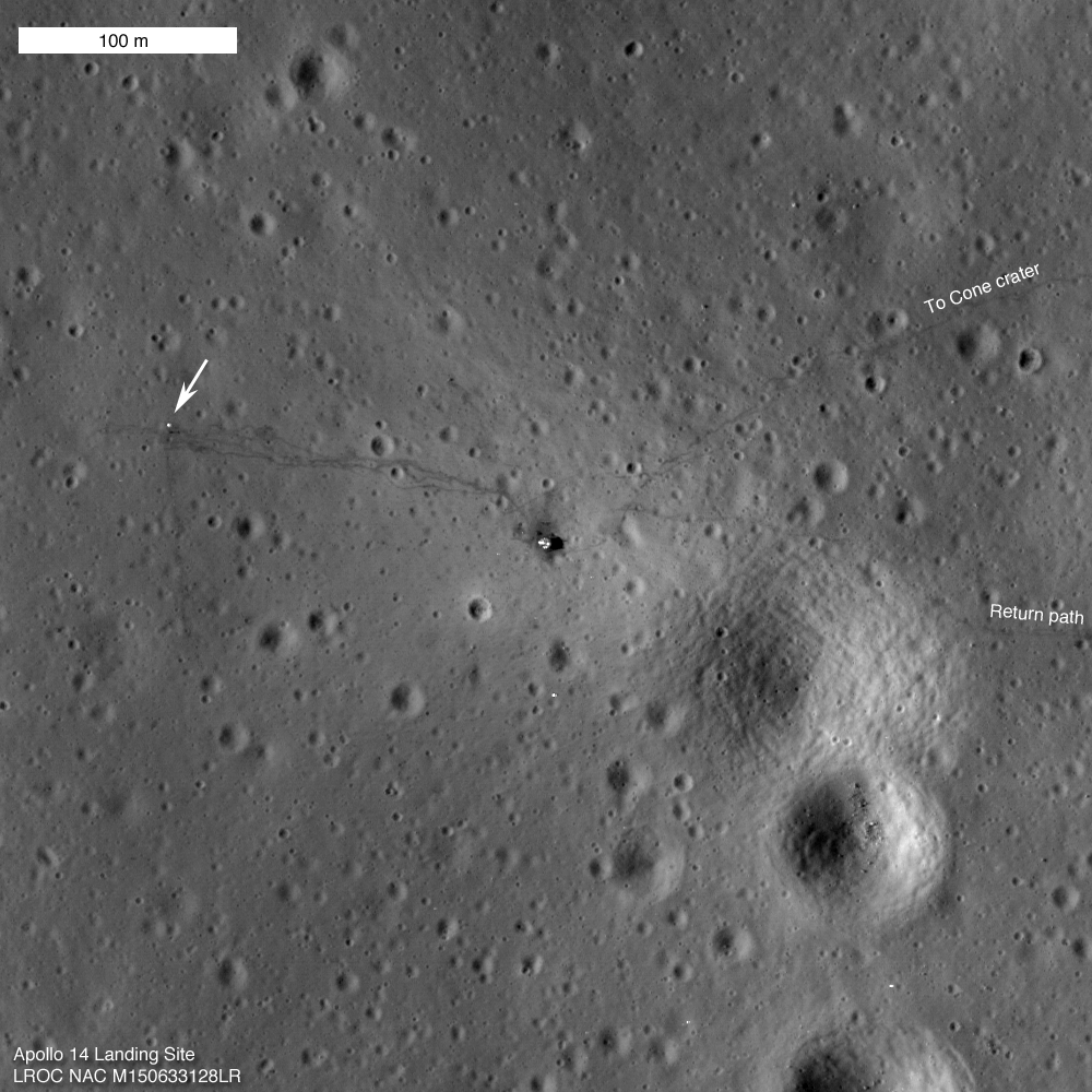
LROC Narrow Angle Camera (NAC) observation M150633128 of the Apollo 14 landing site acquired January 25, 2011 (LRO orbit 7334; resolution = 0.5m). The Descent Stage of the lunar module Antares is at center and the foot paths trailed by Shepard & Mitchell in February 1971 seem totally undisturbed since their departure forty years ago this weekend (field of view 500 meters). Experience the full-sized (1000x1000) LROC Featured Image released February 4, 2011 HERE [NASA/GSFC/Arizona State University].
Mark Robinson
Principal Investigator
Lunar Reconnaissance Orbiter Camera
Arizona State University


The LROC Narrow Angle Cameras continue to image the Apollo landing sites as the mission progresses. Every time LRO passes overhead the Sun is at a different position so each image gives a different perspective. Repeat imaging also serves LROC cartographic goals. Since the position of the lunar modules and other pieces of hardware are very accurately known the LROC team can check the accuracy of the mission-provided ephemeris.

Think of the Apollo sites as benchmarks put in place four decades ago for the LROC team!


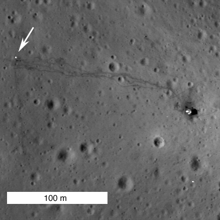
Close-up showing the Apollo 14 Lunar Module's Descent Stage (right) and Apollo Lunar Surface Experiment Package (ALSEP - arrow) with tracks between the two landmarks by Shepard & Mitchell still fresh and distinctive almost precisely 40 years later. In that interval since their departure the foot prints and Apollo 14's deployed materials endured 534 lunar days and nights of relentless exposure, adding to their immeasurable value as sentinel recorders of the lunar environment [NASA/GSFC/Arizona State University].

The Apollo 14 astronauts explored the surface of the Moon on February 5th and 6th, 1971, 40 years ago this weekend. Much was learned during the Apollo missions, yet most of the history and geology of the Moon remains a mystery.

When will we return to the Moon?


Apollo 14 Post EVA view by Edgar Mitchell from inside Antares looking west toward the ALSEP station. LROC PI Mark Robinson suggests matching Edgar Mitchell & Alan Shepard's tracks in this photograph with those in the new LROC NAC view swept up from LRO orbit overhead on January 25, 2011 - forty years later. View the full-resolution high-defintion version of Mitchell's photograph HERE [AS14-66-9338 - NASA/Apollo Surface Journal].

From the Apollo Surface Journal, Apollo 14 Image Library (Magazine 66) "
Ed Mitchell took this splendid picture after he and Al Shepard jettisoned the PLSSs in preparation for launch. Of particular interest are the tracks made by the crew and the MET during the traverse to the ALSEP deployment site and during the return to the LM. Apollo 17 astronaut Jack Schmitt speculates that the descent plume sweeps away the fine particles of soil, leaving a surface dominated by small rock fragments that reflect sunlight from the down-Sun direction and make the surface look lighter in color than normal. In places where the surface is disturbed, the normal reflectivity of the surface is restored. Whatever the detailed explanation for this phenomenon, it is related to the fact that, from orbit, the area immediately surrounding a LM looks noticeably lighter in color. The ALSEP Central Station is about 180m from the LM. Note the excursions the crew made around the rimless crater in the foreground and the large depression in the middle distance that they traversed in both directions. Without the visual clues provided by the tracks, the depression is not easy to pick out in this down-Sun photo. Note that the flag is now pointing on an azimuth of about 335 and undoubtedly moved from it prior pointing of about 120 as a result of the cabin depressurization done for the jettison."

No one to ask for directions: Apollo 14 lunar module pilot Edgar Mitchell finds the "ground truth" of hiking on the Moon, that things can look very different on the surface than from Lunar Orbiter photography from orbit, and he surveys a map while looking for landmarks. Meanwhile Alan Shepard takes his picture near the end of their unsuccessful ascent up the gentle slope to Cone Crater, at Fra Mauro, February 1971. (It was the first time an Apollo expedition had journeyed beyond view of their spacecraft) [AS14-64-9089HR/NASA/ASJ].


A 'true-color' HDTV orbital view, from Japan's SELENE-1 (Kaguya), of the ancient Fra Mauro crater group and material spilled onto this area, south of Copernicus, from the epoch-marking basin-forming impact formimg Mare Imbrium to the northwest ~3.8 billion years ago. The landing site of Apollo 14 is located in the low hills north of the largest of these craters, at upper center. Click HERE for the full-sized original image release [JAXA/NHK/SELENE].

Journey to the Center of the Moon


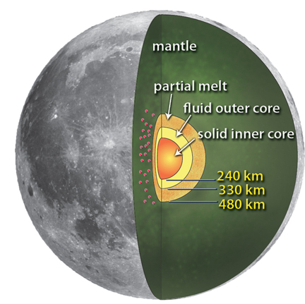
New interpretation of the lunar interior (from Weber et al., 2011, Science 331, 309-312)

Paul D. Spudis
The Once & Future Moon
Smithsonian Air & Space

A recently published science paper presented results of a re-analysis of seismic (moonquake) data sent to the Earth from a network emplaced by the Apollo astronauts 40 years ago. The scientists processing the old data found that the Moon may have more than a simple core – it may have a layered, partly liquid metallic core.

Why is this important? Scientists have known for many years that the Earth has a layered interior structure. The outermost layer, called the crust, is the only part of the Earth directly accessible to us for study. The crust varies in thickness, ranging from a few kilometers in the ocean basins to over 20 km in continental areas. The next zone down is called the mantle. The mantle is very thick – almost 3000 km. It is made up of a dense, iron- and magnesium-rich rock type called peridotite. Partial melting in the mantle is the source of basaltic magma that erupts to make up the floors of ocean basins worldwide. The innermost part of the Earth is the core, comprised mostly of metallic iron and nickel, and over 3000 km in radius. The outer layer of the core is liquid, but the enormous pressure that contains the inner core keeps it solid.

The Earth’s core is electrically conducting as the rotation of the Earth induces currents within it. It is thought that these electrical currents are responsible for the dynamo that generates the magnetic field of the Earth. Because most of the Earth’s iron is contained in the core, we know that in bulk composition, the Earth is made from chondrites, the same stony material found as primitive meteorites in space. Thus, understanding the core is relevant to the origin of its magnetic field and the internal structure and bulk composition of the Earth.

For these reasons, we are interested in the possibility of a core within the Moon. Even before we went to the Moon, we understood that an internal structure similar to Earth was not likely. A property called moment of inertia told us in broad terms that, unlike the layered structure of Earth, the Moon was more or less homogeneous inside. The moment of inertia indicated that any core inside the Moon must be smaller than a couple of hundred kilometers at most (the Moon’s radius is 1740 km).


The Apollo 12 Apollo Lunar Surface Experiment Package (ALSEP) after its deployment in Oceanus Procellarum, November 19, 1969. Among the instruments set up by Conrad & Bean was the Passive Seismic Experiment (PSE). The Apollo ALSEP assets were kept powered by radioisotope thermoelectric generators and data continued to be collected until the project was defunded in 1977, leaving only three laser range reflector arrays as the only remaining Apollo assets contributing new science until the arrival in orbit of LRO in July 2009 [AS12-67-6817-Conrad/Apollo 12].

Seismometers, deployed on the Moon as part of a surface network during the Apollo missions, operated for over seven years collecting data on tremors within the Moon. Because certain rocks have known physical properties (e.g., density), we use the velocity of seismic waves in an indirect way to infer the presence of these rock types and physical structure. From our initial analyses of these data, we determined that the Moon had a fairly thick crust (from 50-80 km, more than twice the thickness of Earth’s crust) and a very thick mantle, almost the remainder of the lunar radius.

The question of the existence of a lunar core remained uncertain. One moonquake resulting from a fairly large impact on the far side of the Moon a couple of years after the Apollo missions had ended produced a signal that suggested the presence of a small core (less than 400 km radius). Moreover, because seismic waves come in two varieties – P-waves, or compression (or sound) waves and S-waves (shear waves, which cannot propagate through liquids) – the partial suppression of S-waves through the center of the Moon during this event suggested that the lunar core might be partly liquid.


The Apollo 14 S-IVB booster (S-IVB-509) was 17.8 meters tall, 6.6 meters wide and weighed about 14,000 kg. It was launched January 31, 1971, and after extraction of the Lunar Module Antares, the S-IVB was directed to dump its remaining fuel directed toward an impact the Moon February 4, 1971. (From "Apollo 14 S-IVB Impact Crater," Mark Robinson, October 8, 2009) "The Apollo impact velocity was 2.54 km/sec at an angle of 69° from the horizontal along a heading of 103° (west to east). The S-IVB had a mass of 14,016 kg at the time of impact and impact energy was 5.54 x 10\10 Joules (equivalent to just over 10 tons of TNT). The signal from the impact was recorded on the Apollo 12 seismometer (PSE) and rebounded throughout the Moon for 3 hours." [NASA/ARC/NLSI].

But this result was so uncertain that few lunar scientists actually believed it. They proceeded to try and constrain the dimensions and composition of a lunar core through other means. A core may be important in the generation of an early global magnetic field that some of the lunar samples seems to indicate (the current Moon has no global field). By carefully measuring the ways in which the magnetic field of the Sun and Earth is modified when the Moon passes through it (as it does during its orbit around the Earth), it was thought that it might be possible to “sense” the presence of a lunar core by measuring these deviations. Results indicated that the core of the Moon had to be small (less than 400 km in radius) and probably made of iron sulfide (FeS).

After seven years of operation, the Apollo seismic net was turned off to save money. Up until it was turned off, we had received a large amount of data but processing it was extremely difficult. The Apollo instruments, although sensitive, were very noisy and not well coupled to bedrock as are seismometers on Earth. Fortunately, faster and more capable computers, along with new techniques to process and analyze noisy data, were developed. And a new generation of scientists came forward to re-examine the old seismic data to see if anything could be discerned from it.

The new results are surprisingly detailed. Not only do these researchers think they have detected a core inside the Moon, but a core with three separate layers – an inner solid core and outer core, very similar in structure to that of the Earth, but with the added wrinkle of a partly molten outermost layer. The entire core is almost 500 km in radius, slightly larger than the diameter inferred from deep magnetic sounding.


LROC Observation M111762553R, LRO orbit 1604, November 2, 2009, from 43.5 km, resolution 49cm/p, solar incidence 31.3° Apollo 14 S-IVB impact at 8.179°S, 333.969°E (from from "LROC Coordinates of Robotic Spacecraft," Samuel Lawrence, April 5, 2010) [NASA/GSFC/Arizona State University].

The presence of currently molten core inside the Moon is rather startling; even the earlier idea about a partly molten zone was viewed askance by most lunar students. But this new idea has revived concepts about a magnetic core dynamo inside the Moon, generating a global field early in lunar history. Such a dynamo might explain a lot about the remnant magnetic fields measured in some of the returned lunar rocks. But there is no obvious reason why such a field would suddenly stop being generated.

Even though the old Apollo network data may still be mined for information, to fully understand lunar structure and history we must emplace a long-lived, global network of new instruments to fully characterize the interior of the Moon. Although studies are underway to determine how this might be accomplished, deployment of such a network is difficult to achieve by robotic spacecraft alone and long life on the Moon may require a nuclear power supply. Each and every time we start believing that we understand our Moon, a new discovery raises even more questions.

Thursday, February 3, 2011

Mendeleev in Full


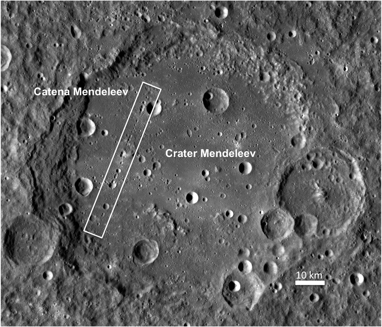
A LROC Wide Angle Camera (WAC) 100 meter/pixel monochrome mosaic released February 3, 2011, shows all of Mendeleev (313 km in diameter) in a full-sized dramatic view available HERE. The white rectangle marks the location of Catena Mendeleev, highlighted in greater detail HERE and below [NASA/GSFC/Arizona State University].

Sarah Braden
LROC News System

Mendeleev crater (named after Dimitri Mendeleev, the inventor of the periodic table of elements) is a very large, Nectarian-age crater on the lunar farside (5.7°N, 140.9°E). Approximately 313 kilometers in diameter, it is almost large enough to be a small basin. The interior contains many younger craters, including Catena Mendeleev, but also features a very smooth floor filled in with a light plains material. In general, this material is characterized by its smooth surface and intermediate albedo (brighter than basaltic mare material, but not as bright as highlands material). Light plains are found elsewhere on the Moon, most notably in the Cayley formation, the Apollo 16 landing site. Light plains are usually thought to be emplaced as large scale grounding flows of ejecta from large basin forming impacts. However details of this formation mechanism are still not well understood.


A fanciful view of the newly-released LROC WAC mosaic, tapered into the lunar digital elevation model available to users of Google Earth (>v.5). In the foreground left Richards crater (7.7°N, 140.1°E) is approximately 9 km in diameter [NASA/GSFC/Arizona State University/USGS/JAXA].

Explore the entire WAC mosaic here!

Related Posts:
Hunting for Ancient Lunar Impact Basins
Mare Frigoris


In 2007, Japan's robust first lunar orbiter SELENE-1 ("Kaguya") took high color High Definition television views from orbit, including this still of Mendeleev from around 100 kilometers above and several hundred to the south, as all of the 313 km crater lingered momentarily on the orbital horizon. Click HERE to see the full-sized image [JAXA/NHK].

Wednesday, February 2, 2011

Inside Catena Mendeleev


Texture on inside wall of a crater in the Catena Mendeleev, a linear crater chain located inside the 313km Mendeleev crater (5.7°N, 140.9°E), detail from LROC Narrow Angle Camera observation M113038958R, solar illumination incidence angle 46°, image resolution 0.5 m/pixel; LRO orbit 1792, November 16, 2009. View the full-sized original LROC Featured Image, HERE [NASA/GSFC/Arizona State University].

Sarah Braden
LROC News System

Catena Mendeleev is a linear crater chain probably formed by the impact of fragments (called 'secondaries' by planetary scientists) that were ejected by the impact that formed Tsiolkovskiy Crater, 850 kilometers to the southwest of Mendeleev. Crater chains form from secondary impacts ejected radially from their parent impact.

Today's Featured Image shows the rough and smooth textures on the inside of one of these secondary impacts. Secondary craters in a chain are often elongate in shape, with irregular rims. Secondary crater chains tend to occur in a zone immediately surrounding a large primary crater. However, larger impacts can move significant amounts of ejecta, including crater chains, far from the primary crater, as we see here at Catena Mendeleev.


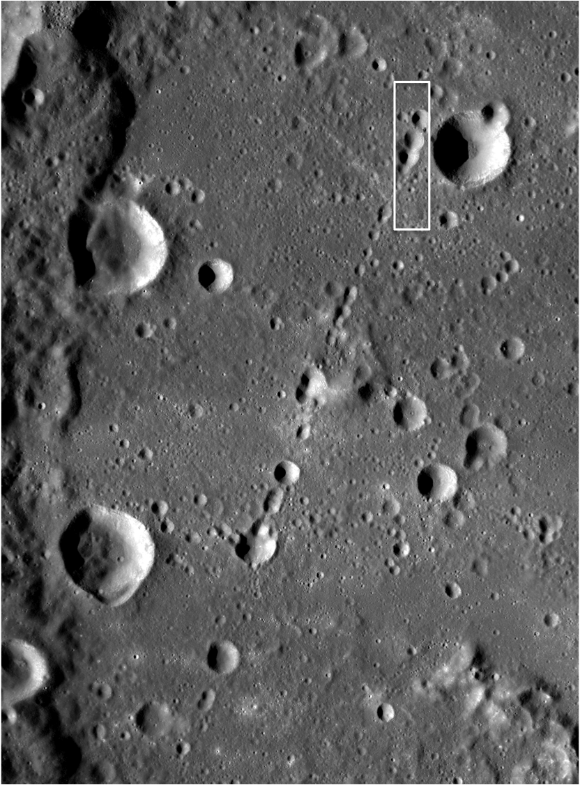
LROC Wide Angle Camera 100 m/pixel monochrome mosaic, annotated with a white box marking the location of LROC NAC observation M113038958 field of view, centered at 7.67°N, 139.62°E, within Mendeleev Crater [NASA/GSFC/Arizona State University].


Backing away further from the field of view above allows for even more context, using the LROC WMS Image Map. The full-extent of the relatively flat interior of 313km-wide Mendeleev in comparison with the rolling highlands typical of the lunar farside comes into view [NASA/GSFC/Arizona State University].

Browse the full NAC frame to explore the craters in Catena Mendeleev!

Related Posts:
Chain of secondary craters in Mare Orientale
Stream of Secondary Craters

Tuesday, February 1, 2011

Farside Stratified Ejecta Blocks


A stratified ejecta block around an unnamed fresh crater on the far side of the Moon, LROC Narrow Angle Camera observation M110757216R, LRO orbit 1456, October 21, 2009 (frame centered near 13.13°N, 127.61°E). Solar incidence angle is 24°, scale is 0.58 m/px [NASA/GSFC/Arizona State University].

Sarah Braden
LROC News System

An unnamed, young Copernican crater (about 8.6 km in diameter) northeast of crater Meshcherskiy, has a diverse collection of impact ejecta features. In today's featured image we see evidence for stratified materials in the ejecta blanket of the crater. This particular block, about 170 meters across (approximately two football fields long), might have formed through the impact process, or perhaps the stratified layers are consolidated (compressed) regolith. During an impact, material is thrown out of the crater cavity in sheets of material called ejecta. With the right conditions, the sheets of ejecta could form the layers of the block seen here. It is also possible that the layered material existed before the impact. The simplest explanation is that the layers we see here are actually linear stress fractures in a continuous block, due to the strength properties of the rock. Can you find similar layered rocks in other NAC images elsewhere on the Moon?


Another 80 meter-long section of ejecta, from the same crater and NAC frame appears also to have stratified layer (left side of image) [NASA/GSFC/Arizona State University].

Backing away from LROC NAC M110757216R shows debris fans falling back into the crater's interior. This close-up view of this relatively "fresh" (Copernican) crater provides the opportunity to examine lunar features before their distinctive rougher edges are pulverized by relentless bombardment by even fresher impacts, near and far, large and microscopic [NASA/GSFC/Arizona State University].

Context for the the dramatic LROC NAC frame M110757216, centered near 13°N, 127°E, 750 kilometers southwest of Mare Moscovienese [LROC WMS Image Map/Arizona State University].

Browse the rest of the ejecta blanket in the NAC frame.
Related Posts:
Recent Impact
Impact Melt Flows on Giordano Bruno

Students study lunar samples

From Album LP4
Trinity Academy eighth-graders Gabrielle Fatula and Steven Wargo engage in a mock tug-of-war over a display of Apollo lunar samples on loan from NASA for Catholic Schools Week at Trinity Academy in Shenandoah, Pennsylvania. The display, together with meteorite samples and student-made displays will be open for public viewing Wednesday, February 2, from 6 to 8 p.m.

John E. Usalis

The students at Trinity Academy in Shenandoah won't have to go to the moon to see lunar soil and rocks. The items came to them.

Thanks to Trinity science teacher Michael Kowker, samples of the lunar material collected by the astronauts of the Apollo space program will be on display to the public Wednesday from 6 to 8 p.m. at the school as part of Catholic Schools Week.

Protected in a plastic case, the samples will provide students and visitors to the school a chance to see some of the lunar materials up close, which for many would be their first opportunity.

"The lunar samples are not the largest in the world, but I thought it was a neat idea to get them here and let people see the moon," Kowker said in his classroom, which has many space-related images on the walls.

Kowker's connection to the lunar materials came through a workshop he attended in the summer at Penn State University Park.

"The workshop was sponsored by NASA and the Pennsylvania Space Consortium," Kowker said. "It was a weeklong seminar on lunar exploration. There were about 30 teachers in attendance. We did investigations on the theories of lunar formation, the structure, chemical composition, some of the new discoveries, such as they found water, and, of course, the Apollo missions. There was a representative from NASA at the workshop, and we got certified to request these samples from NASA in Houston."

The samples were provided through NASA's Johnson Space Flight Center and were collected by the astronauts from the Apollo 14 through 17 space flights. Kowker said there are about 80 similar sample displays that are available to be loaned to schools around the country. Elementary and high schools get the smaller samples, while colleges can get larger samples.

"I don't know if it's a once-in-a-lifetime opportunity, but it was something I never had to request the samples, but once I got my certificate, I thought it would be great for the kids and the community to see," Kowker said. "One of the samples is a rock from the highland regions along the equator of the Moon collected in Apollo 16. They think that rock is 4.5 billion years old, which would be from the original lunar crust."

Kowker said many people remember watching the Moon landings and the astronauts walking on the lunar surface, and this display brings them closer to what they saw.

"I was a just a pre-schooler at the time when they landed on the Moon," Kowker said. "Maybe I sat there and watched it, but I've done a lot of reading and could see the excitement of the whole thing, and 'Wow! This is the Moon.'"

Read the full story, HERE.