Sunday, February 27, 2011

Vision statements for non-Visionaries


The best of Armstrong's photographs of the Apollo 11 mission's commemorative plaque, attached to the Eagle's forward strut behind the Descent Stage ladder, July 20, 1969. Dr. Paul D. Spudis suggests in his latest blog post "editing" may be "needed to accommodate NASA's latest "vision" statement [NASA/ASJ].

Paul D. Spudis
The Once & Future Moon
Smithsonian Air & Space

A seemingly trivial event has revealed some schadenfreude about NASA, along with a lot of irritation. Apparently (as is their wont) the fertile minds running our national space agency decided that the time has come (once again) for a new and improved vision statement – out with the old and in with something new. These would be harmless exercises except to the extent that taxpayer money is being spent to no real purpose (but if I got into that, there’d be no end to this post).

I want to specifically address the newest agency vision statement. It reads: “To reach for new heights and reveal the unknown so that what we do and learn will benefit all humankind.” Beyond being generous, well meaning and philanthropic, what new vision can be found here? Should we not “reach for new heights”? Isn’t the job of an agency devoted to exploration to “reveal the unknown”? And why not do all this “for the benefit of all humankind?” The first order of any lunar return must certainly be to replace that ill-conceived plaque that’s already there – “We came in peace for all mankind.” Actually, “all kind” has a certain ring about it – perhaps on the next go-around.

I could vent my spleen about the utterly vacuous nature of the new slogan. I could point out that nothing in it requires NASA (or any other entity) to actually conduct missions into space, or in fact, to do anything at all. I could find many who, like me, understand that this new slogan reflects the fact that the agency understands that it has no real mission and has employed a wordsmith to design the appropriate phrasing for such a situation.

I have written previously about the management fads that periodically sweep through the agency – the alphabet soup of TQM to Earned Value to Continuous Improvement. American industrial life is awash with self-help management cults that variously are employed to convince agency personnel they really need to become managers because NASA needs more people to manage meetings and seminars about all of the wonderful things they are going to do in space. NASA is most certainly not immune to this tendency and indeed often among the first to embrace new management fads as soon they come out of the box.

What does this say about the state of our national space program? As a longtime student and participant of many things NASA, I feel uncomfortable saying it’s because no one in charge of the agency can say (or cares to say) why we have a space program or what its mission is — or what they would do if they had one. This is not to say that there aren’t good reasons for a space program or that there aren’t people who work for NASA who do in fact know what they are trying to do. I believe that NASA dropped the ball in implementing the Vision for Space Exploration because they never took the trouble to understand exactly what it meant – that they forgot about what having a vision means beyond the obvious articulation of some destination. Clearly, you cannot see a way forward to implement what you do not understand.

Twenty years ago, NASA got a new administrator, someone who (it was fervently hoped) would breathe new life into the moribund organization. Daniel Goldin was a “take charge” guy, someone who had been successful in the commercial and defense space sector at TRW. Goldin came to NASA ready to shake things up – he reinstated NASA’s classic Technicolor “meatball” logo and claimed to want to hear all opinions. I was invited to a “Meet the New Administrator” meeting soon after he took office. During the meeting, he was thoughtful and listened carefully while about a dozen of us from a variety of backgrounds kicked around some ideas about the mission of NASA. Then, in the middle of this all-day brainstorming session, he suddenly excused himself and left. He returned a bit later, breathless and with great excitement, announced to us: “I’ve just spent the last 2 hours with Carl Sagan!”

Uh-oh. I knew what that meant. The new “mission” of NASA was to be a “Quest for Life.” And sure enough, searching for life became the mantra of NASA’s mission under Dan Goldin. But by making “the search for life” their mission, NASA faced a problem – if they didn’t find it, their mission could be considered a failure. So, in order to survive the new “mission,” the Quest for Life gradually morphed into the search for water (on Mars). After all, water is required for life. So the mission objective mutated from a long-shot miracle to something reasonably certain. It fit. No one would be seen as not fulfilling NASA’s mission and they could continue to look for water on Mars and dream of discovering new life.

Anyway, as I said, vision statements come and go. No doubt the new one will last about as long as the current occupants of NASA Headquarters.

Oh, what was my brilliant suggestion for a “vision statement,” you ask?

“To explore the universe with people and machines.”

Succinct – to the point – all-inclusive.

But what do I know?


Dr. Spudis has just published "Blogging the Moon," a collection of postings to his Smithsonian Air & Space blog "The Once & Future Moon."

The Moon's metallic water


The LCROSS Shepherding Spacecraft Mid-Infrared Camera (MIR) captured this false-color image of the Centaur impact ejecta plume about 20 seconds after impact, October 9, 2009 [NASA/ARC/LCROSS].

Bill Steigerwald

NASA Goddard

Bring a filter if you plan on drinking water from the moon. Water ice recently discovered in dust at the bottom of a crater near the moon's south pole is accompanied by metallic elements like mercury, magnesium, calcium, and even a bit of silver. Now you can add sodium to the mix, according to Dr. Rosemary Killen of NASA's Goddard Space Flight Center in Greenbelt, Md.

Recent discoveries of significant deposits of water on the moon were surprising because our moon has had a tough life. Intense asteroid bombardments in its youth, coupled with its weak gravity and the Sun's powerful radiation, have left the moon with almost no atmosphere. This rendered the lunar surface barren and dry, compared to Earth.

However, due to the moon's orientation to the Sun, scientists theorized that deep craters at the lunar poles would be in permanent shadow and thus extremely cold, and able to trap volatile material like water as ice if such material were somehow transported there, perhaps by comet impacts or chemical reactions with hydrogen, a major component of the solar wind.

The October 9, 2009 impact of NASA's Lunar CRater Observation and Sensing Satellite (LCROSS) spacecraft into the permanently shadowed region of the Cabeus crater confirmed that a surprisingly large amount of water ice exists in this region, along with small amounts of many other elements, including metallic ones.

Read the full feature, HERE.

Friday, February 25, 2011

Fragmented Impact Melt


Western floor of the fresh crater Giordano Bruno, LROC Narrow Angle Camera M110919730L, 0.61 m/pixel, field of view is about 737 meters, illumination is from the lower right, at an incidence angle of 42° View the full-sized image HERE [NASA/GSFC/Arizona State University].

Hiroyuki Sato
LROC News System

Today's Featured Image looks like a parched Arizona mudflat after a monsoon downpour. Not quite! You are looking at the broken surface of an impact melt pond inside Giordano Bruno crater. A surface crust fragmented into angular blocks up to about 40 meters in width as still molten rock was drained from beneath a hardening crust. The small clusters of relatively bright rock fragments are likely boulders that rolled down from the nearby steep walls.


Context map around Giordano Bruno crater. LROC Wide Angle Camera 100 meters/pixel mosaic. Blue rectangle, centered near 36.09°N, 102.83°E. corresponds to the footprint the LROC frame from which the LROC Featured Narrow Ange Camera Image was sampled. View the full-sized WAC image map sample HERE [NASA/GSFC/Arizona State University].

Explore lunar melt ponds by viewing the full NAC frame!

Related Featured Images:
Giordano Bruno impact melt flows and ejecta flows

Thursday, February 24, 2011

Mounds in a melt pond


Deep interior of Laplace A crater, LROC Narrow Angle Camera (NAC) M129466485R, corrected resolution 0.80 m/pixel, field of view 960 meters; sunlight from southeast, incidence 66° (LRO orbit 4213, May 25, 2010) Full-sized LROC Featured Image HERE [NASA/GSFC/Arizona State University].

Hiroyuki Sato
LROC News System

During an impact event the kinetic energy of the meteorite is dissipated by compression, fragmentation, excavation and launching rock debris -- all resulting in an impact crater. The large amount of energy released also melts some of the target rock, and often times impact melt ponds form in the floor of the crater. Since the impact melt is liquid, it seeks an equi-potential level (surface is perpendicular to the gravity vector), thus it is flat and smooth as it freezes.

Today's Featured Image reveals the bottom of Laplace A crater, specifically the north edge of its impact melt pond. The upper side of this image corresponds to the lower part of crater wall, covered by lots of boulders. The surface of this melt pond consists of dozens of low mounds, possibly due to deformation of the pond surface after partial solidification. Perhaps rebound of the crater floor caused the level of molten material beneath the crust to rise and create small breakouts to the surface. There is also a cone shaped depression near these mounds. It may have formed as magma drained out from below?


Inset from full-sized context map (HERE) shows the rich detail of the vicinity of Laplace A, the largest crater in the "mouth" of Sinus Iridium, south of Promontorium Laplace (upper right). LROC Wide Angle Camera (WAC) 100 meter/pixel monochrome global mosaic, overlayed by WAC color Digital Terrain Model (500 m/p). The blue long box over Laplace A corresponds to the footprint of the right-hand frame of LROC NAC M129466485 from which the LROC Featured Image above was derived [NASA/GSFC/Arizona State University].

Explore lunar landslides by viewing the full NAC frame!

The topographic color was produced as a by-product of stereo analysis of the WAC global dataset. Producing the global Digital Elevation Model (DEM) is a big job being led by LROC team members at the German Aerospace Center (DLR; English version) in Berlin.

Related Featured Images:
Impact melt features in Tycho crater's floor
The Floor of Tycho - Constellation ROI
Central Peak of Rutherfurd
More Impact Melt!


General location of the LROC Featured Image, February 24, 2011, within the wider context of the larger width of LROC NAC frame M129466485R [NASA/GSFC/Arizona State University].


It's unfair, really, to seemingly disparage this amazing view as being among the "middle range" of available resolutions in the current harvest from international lunar robotic missions. A 3D view of Laplace A as viewed at or near perilune during a high-priority survey of Sinus Iridium, (possible landing site for China's first lunar lander) from China's second lunar orbiter Chang'E-2, released last October 28, 2010. A larger version of the image is available HERE [CNSA/CLEP].

From LROC WAC Sample Album
Inset from uncorrected LROC WAC frame M120026575ME showing Laplace A, swept up during LRO orbit 2822 from an altitude of 36.36 km; resolution 50.92 meters/pixel, February 5, 2010. [NASA/GSFC/Arizona State University].

Dark streaks in Diophantus crater


Dark streaks down the steep inside northern rim of 19km Eratosthenian crater Diophantus (27.6°N 325.6°E) in southwest Mare Imbrium. LROC Narrow Angle Camera (NAC) frame M124797072L; 0.56 m/pixel, field of view about 678 meters, with Illumination from the south; downslope is from top to bottom. View the full-sized Featured Image HERE [NASA/GSFC/Arizona State University].

Hiroyuki Sato
LROC News System

Today's Featured Image reveals the upper slopes of Diophantus crater, located on the western edge of Mare Imbrium. The upper dark area of this image corresponds to the flat mare surface, outside of the crater. The most striking feature here is the dark material that flowed down the crater wall. The reflectance of surface materials is controlled by various factors such as sunlight direction, grain sizes and surface textures, and composition. In this picture, the dark materials are most likely a different composition (relatively bright materials also flowed down-slope next to the dark flows).

These dark features originate from several layers exposed in the crater walls. The horizontal extent of these layers is rather discontinuous and they appear at various elevations; their thickness ranges from five to ten meters. What material composes these dark slides? We know from samples returned from the Apollo 17 mission that very dark pyroclastic materials (explosive volcanics) exist on the Moon. Perhaps these slides are a layers of pyroclastics that were buried by younger lava flows. When Diophantus was formed these layers were exposed! There is much to be learned about the distribution and chemistry of pyroclastics and in turn about the deep interior of the Moon. Imagine future astronauts rappelling down to sample these exposures!


Digital Terrain Model (DTM) context map of a large area surrounding Diophantus with a rectangular strip, located at 326.34E, 27.63N. Product is from a LROC Wide Angle Camera (WAC) 100 meter-per-pixel monochrome global mosaic overlayed by WAC color DTM 500 meter-pixel survey by DLR of Germany. The rectangle corresponds to the footprint of the LROC NAC frame from which came the LROC Featured Image, February 23, 2011. View the full-sized context map HERE [NASA/GSFC/Arizona State University].

Explorer lunar landslides by viewing the full NAC frame!

The topographic color was produced as a by-product of stereo analysis of the WAC global dataset. Producing the global Digital Elevation Model (DEM) is a big job being led by LROC team members at the German Aerospace Center (DLR; English version) in Berlin.

Related Featured Images:
Color of the Moon
Volcanoes in Lacus Mortis
A Dark Cascade at Sulpicius Gallus


Foreshortened view of the LROC Featured Image (February 23, 2010) supported by the full left and right NAC frames M124797072 and the digital elevation model available to users of Google Earth (versions 5 and above) [NASA/GSFC/Arizona State University].


From the southern rim, a simulated view of the interior of Diophantus overlaid with the left and right frames of LROC NAC M124797072 and the "free air" elevation range from the dark streaked terrain just inside the crater's northern rim and the deep interior [NASA/GSFC/Arizona State University].


Diophantus, supporting Diophantus C on its southwestern rim, swept up in LROC Wide Angle Camera observation M117718865M before local sunset, from 38.8 km up during LRO orbit 2482, January 9, 2010 [NASA/GSFC/Arizona State University].

Wednesday, February 23, 2011

High-speed lunar navigation for crewed and remotely-piloted vehicles


Figure 2 - NASA’s K10 autonomous or teleoperated rover designed for robotic site survey, at speeds up to 0.6 m/s. (Houghton Crater K10 Field Test, 2010) [NASA/ARC/NLSI].

Pedersen & Allan, et al.
NASA Ames Research Center
Carnegie Mellon University
Humboldt University
ETH, Zurich


Increased navigation speed is desirable for lunar rovers, whether autonomous, crewed or remotely operated, but is hampered by the low gravity, high contrast lighting and rough terrain. We describe lidar based navigation system deployed on NASA’s K10 autonomous rover and to increase the terrain hazard situational awareness of the Lunar Electric Rover crew.

Introduction - High speed mobility (by planetary rover standards) is desirable for more efficient exploration of the lunar surface, particularly if human crews are present there.

NASA’s Lunar Electric Rover (LER) can drive at 10km/h (3m/s) on rough terrain, faster on known smooth surfaces. By comparison, the MER vehicles moves at a few cm/s while stopping regularly.

Driving on the Moon is complicated by the low gravity, rough terrain, high contrast lighting and alien environment.

Under the 1/6g lunar gravity a vehicle becomes airborne at relatively modest speeds (driving the Apollo era lunar rover at 7 mph was reportedly like being aboard a rowing boat for this reason). The reduced gravity also lessens vehicle-ground friction. Together these effects increase maneuvering distances.

Astronauts complained of difficulty discerning surface features on the Moon under certain lighting conditions, such as with the sun behind them. The lack of terrestrial depth cues compounds the difficulties of driving.

The 3 sec signal round trip time delay to the Moon permits tele-operating a vehicle from Earth (e.g. Lunakhod) with diffculty (increasing with speed).

This paper describes our robotic rover navigation systems, currently running on NASA’s autonomous or teleoperated K10 rover (Figure 2) and as a crew aid on the LER for increasing pilot situational awareness of the surrounding terrain. We address terrain sensing for 4 different classes of rovers: K10, the Lunar All Terrain Utility Vehicle (LATUV, Figure 3), the LER and the LER operating under lunar gravity and time-delayed tele-operation.

Subsequent sections describe the terrain mapping and hazard detection software, pose estimation, the rover software infrastructure for command and data handling, the graphical user interface and performance figures.

Read the Full Abstract, HERE


Figure 8 - Apollo 17 Station 3 high-resolution pan centered on the south rim of Ballet Crater; frames AS17-138-21155 through 21167 assembled by David Harland for the Apollo Surface Journal [NASA/JSC].

i-SAIRAS 2010. 10th International Symposium on Artificial Intelligence, Robotics and Automation in Space - Sapporo, Japan, August 29 - September 1, 2010

Tuesday, February 22, 2011

LROC: Morphometry of lunar volcanic domes


Tran, Robinson & Lawrence
Braden, Plescia, Hawke, Jolliff, Stopar &
the LROC Team
Arizona State University
Applied Physics Laboratory
Hawaii Institute of Geophysics and Planetology
Washington University


Introduction: Lunar domes have long held the interest of the lunar science community, but their origin and composition are still not well understood. Previous studies, using Lunar Orbiter, Apollo, Clementine, and LRO data, have proposed several formation mechanisms, and all agree that most lunar domes are volcanic features [1-9].

In anticipation of the 42nd Lunar & Planetary Science Conference, we continue highlighting some of the announced presentations related to lunar science:
We investigated the morphometry and morphology of Gruithuisen, Mairan, Compton-Belkovich, Hortensius, Rümker Hills, and Marius Hills domes using Lunar Reconnaissance Orbiter Camera (LROC) Narrow Angle Camera (NAC) derived digital terrain models (DTMs). These six regions cover two distinct classes of domes, mare and nonmare. The nonmare Gruithuisen, Mairan, and Compton-Belkovich domes have a higher albedo and a strong ultraviolet absorption.

These domes generally have steeper slopes, are high in silica and thorium [3,10,11], and low in iron and titanium [6]. In comparison, mare domes have shallow slopes, lower albedo, and generally weaker UV absorption, presumably due to lower-viscosity mare basalt [1].

Data Sources: NAC stereo pairs were reduced to DTMs with a posting of 2.0-5.0 m using standard photogrammetric techniques and were controlled to the LOLA reference frame [12]. The vertical precision error for the 2.0 m/post DTMs is less than 11 m, and the vertical precision error for the 5.0 m/post DTMs is typically less than 5 meters. The absolute accuracy of the DTM largely depends on the accuracy of the LOLA data, currently within 1 m radial [13] and 50 meters horizontal [14].

Figure 1 illustrates the topography and slopes of a dome in Compton-Belkovich as an example of the results. Figure 2 illustrates examples of the topographic profiles that can be extracted from the DTMs, in this case for Gruithuisen NW and Hortensius. Data for each of the domes examined are presented in Table 1.

Results: Mairan T dome is located west of Mairan crater, is symmetrical in planform, and is interpreted to have originally formed on highland material and subsequently embayed by mare basalt [2]. Slopes on the flank range from 22° to 27° and have a well-defined contact with the mare. At the summit is a depression, ~3.8 km wide and up to 450 m deep, likely formed from collapse associated with magma withdrawal. The slope of the walls of the depression are 13° to 25° and the depression has a flat floor.


Highly reduced 10000 samples and 15000 lines of LROC Narrow Angle Camera observation M127247376LR (down to 400x800 resolution above) shows half of the Marian T dome and the eastern half of its steep slopes, rising ~770 meters from its contact with the Oceanus Procellarum floor. LRO orbit 3886, April 30, 2010 [NASA/GSFC/Arizona State University].

Gruithuisen NW dome is a small dome relative to Gruithuisen δ and Gruithuisen γ. The smaller dome is situated on highland material and is similar to Mairan T with slopes of 22° to 27°. The dome exhibits a summit plateau ~2.5 km in diameter.


Gruithuisen NW, crowded by the larger (20 km-wide) of the two domes (AKA Mons Gruithuisen Gamma - 36.0°N, 319.5E°), at below right of center. LROC WAC observation M117759764ME, LRO orbit 2428. January 10, 2010 [NASA/GSFC/Arizona State University].


Another highly reduced (down to 400 x 800 from the 15000 x 10000 pixel original) close-up of the northwestern of the two domes in the WAC observation immediately above, this time a center slice of both the left and right frames of LROC NAC observation M114226267, LRO orbit 1967, November 30, 2009 [NASA/GSFC/Arizona State University].

The Compton-Belkovich region is a localized thorium anomaly located on a topographic rise between Compton and Belkovich craters [15]. The largest of several domes is located on the northern edge of the region. Its diameter is ~6.8 km, with a height of ~575 m from the southern base and ~950 m from the northern base. Flank slopes are generally 20° to 26° except on the northwest flank where slope gradually decreases from ~16° to 12-13°. Unlike the Gruithuisen NW and the Mairan T domes, where the dome has an abrupt change in slope near the base, this dome has a gradual change in slope, merging with the surrounding surface.


Figure 1. Color-shaded relief map (top) and slope map (bottom) of Compton-Belkovich Dome 1.

The Hortensius Domes are mare domes located north of Hortensius crater in Mare Insularum. The four domes that were analyzed are numbered Hortensius 1, Hortensius 2, Hortensius 3, and Hortensius 4. These domes are broad low-relief features having a gradational contact to the mare. Hortensius 2 and 3 each have one summit crater, Hortensius 1 has two summit craters, and Hortensius 4 has no summit crater. All of the summit craters are slightly offset from the dome peaks, and the depth of the craters are the same or slightly smaller than the height of the domes. The d/D ratio for all four craters is between 0.14 and 0.17. All of the summit craters but one are rimless, implying a non-impact origin. The crater on Hortensius 1 has a rim up to 35 m high, which may indicate an impact origin or late stage viscous materials.


Hortensius (6.5°N, 332.0E°) and four of the 15km-wide crater's nearby namesake volcanic domes, referenced in MORPHOMETRY OF LUNAR VOLCANIC DOMES FROM LROC, 42nd Lunar and Planetary Science Conference (#2228), Tran, Robinson, Lawrence, et al. LROC Wide Angle Camera (WAC) monochrome (643nm) observation M120039376, LRO orbit 2824, February 5, 2010 [NASA/GSFC/Arizona State University].

The Rümker Hills are situated on an elevated mare region in Oceanus Procellarum [16]. Flanks of the domes show a distinct ridged texture, and the majority of summit craters are degraded with low d/D ratio. The three domes that were analyzed are the western flank of Rümker Hill 1, the eastern flank and summit crater of Rümker Hill 2, and the western flank of Rümker Hill 3. The NAC DTM overlaps with the summit crater in Rümker Hill 2, and its d/D ratio is ~0.08.


Necessarily foreshortened view of the Rümker Hills, in an idealized line-of-sight view from Earth, from the LROC WAC mosaic of the lunar nearside released February 21, 2011 [NASA/GSFC/Arizona State University].


Mons Rümker (41.0°N, 301.1E°), itself a 71-km-wide dome plateau in north Oceanus Procellarum, along with three of its hosted volcanic domes as referenced in MORPHOMETRY OF LUNAR VOLCANIC DOMES FROM LROC, 42nd Lunar and Planetary Science Conference (#2228), Tran, Robinson, Lawrence, et al. LROC Web Map Server (WMS) image search engine map [NASA/GSFC/Arizona State University].

The Marius Hills complex, located in Oceanus Procellarum, has the largest concentration of volcanic features on the Moon [5,7,8]. The majority of domes are irregularly shaped, suggesting changes in lava composition or eruption rates (or both). Two domes were examined: Marius Hill 1 and 2. Both have irregular slopes varying between 5-23°. Both of the analyzed domes have a rough summit plateau; Marius Hills 1 has a smaller cone-like feature superimposed, possibly representing multiple vents, compositional changes, or variability in eruption rate.


The heart of the Marius Hills (12.0°N, 306.0E°), the most extensive dome field on the Moon, identified by China's researchers as one enormous volcano dominating central Oceanus Procellarum. The largest two domes, are seen here south of the familiar sinuous rilles at local sunrise, LROC WAC monochrome (689nm) observation M116683214ME, LRO orbit 2329, December 29, 2009 [NASA/GSFC/Arizona State University].

Discussion: Flank slopes on the domes fall into two categories: steep (greater than 20°) and shallow (less than 10°). For terrestrial volcanic constructs [17], steep slopes are typically associated with relatively silicic (e.g., rhyolitic) domes such as those of the Owens Valley [18-20]. Shallow slopes are typically associated with low viscosity, basaltic-style eruptions. In fact, the mare domes may be more accurately referred to as low shields rather than as domes. The composition of all the lunar domes currently is not well understood.


Table 1. Height is relief with respect to the surrounding terrain. D is average basal diameter. Slope is average flank slope measured across the width of the entire flank.


Profiles: 5x vertical exaggeration

Monday, February 21, 2011

Nearside Spectacular!


LROC Wide Angle Camera (WAC) "no slew" mosaic of the lunar nearside, December 2010. See the Full-Size image release HERE [NASA/GSFC/Arizona State University].

Mark Robinson
Principal Investigator
Lunar Reconnaissance Orbiter Camera
Arizona State University


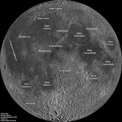
For two weeks in mid-December 2010, the LRO spacecraft remained nadir looking (straight down) so that the LROC Wide Angle Camera (WAC) could acquire ~1300 images, allowing the LROC team to construct this spectacular mosaic. As the Moon rotated under LRO's orbit, the ground track progressed from east to west (right to left in this mosaic), and the incidence angle at the equator increased from 69° to 82° (at noontime the incidence angle is 0°).


Same LROC WAC mosaic of the lunar nearside with major mare basins and craters labeled. The Moon's diameter is 3474 km (2159 miles). View the Full-Size annotated image HERE [NASA/GSFC/Arizona State University].

The LROC WAC is quite small, easily fitting in your hand. It weighs in at only 900 grams (2 lbs). Despite its diminutive size, the WAC maps nearly the whole Moon every month, in 7 wavelengths. The LROC WAC was designed, built, and calibrated at Malin Space Science Systems (MSSS) in San Diego, CA.


LROC WAC mounted on a rotation stage at the MSSS calibration facility in July 2008. The width of the VIS (Visible Light) baffle, indicated with arrow, is only 15.5 cm (6.1 inches) [M. Robinson photo].

Find your favorite nearside features in the 24,000 sample by 24,000 line WAC mosaic.

Previous large-scale WAC mosaic postings:
Eastern Hemisphere
North Pole
South Pole
South Pole illumination
Orientale Basin
South Pole-Aitken (SPA) Basin


Zoom in sample of the LROC Featured Image, February 21, 2011, the LROC WAC nearside mosaic, to maximum resolution. Readily picked out are the familiar landmarks of the Descartes Formation southeast of the Apollo 16 landing site, north of the battered, ancient 30 km wide Descartes Crater. [NASA/GSFC/Arizona State University].

Friday, February 18, 2011

LROC: Sinuous Chain of Depressions


A single depression from a larger sinuous chain of pits located at 34.6°N, 316.5°E, from LROC Narrow Angle Camera (NAC) frame M102443238R. This chain may host uncollapsed lava tubes between the depressions suitable for human habitation. Field of view 1.5 km, solar incidence from the west at 78° Full-sized Featured Image HERE [NASA/GSFC/Arizona State University].

Sarah Braden
LROC News System

This unnamed sinuous chain of pits was suggested to be a collapsed lava tube (see Wilhelms' Geologic History of the Moon). New high resolution NAC images (e.g. M102443238R) provide a new look at the area. This particular feature transitions from a discontinuous sinuous rille into an equally discontinuous wrinkle ridge.


Future Spaceport? Near 35.34°N, 317.57°E, the "Rimae Gruithuisen" chain-rille complex might conceal overlapping 'sublunarian' lava channels, in a part of Oceanus Procellarum replete with the iron and titanium oxide proxies that might mark some of the Moon's deepest reserves of Helium-3, among other promising resources. One day, perhaps a city may spread along the 50 km length of the Gruithuisen chain rille, its residents at least as sheltered from solar storms and cosmic rays as anyone living at sea level on Earth. LROC NAC M102443238L&R, field of view ~5.8 km [NASA/GSFC/Arizona State University].

Some scientists have suggested that wrinkle ridge faults interact with lava tubes, with the wrinkle ridge exploiting a zone of mechanical weakness (the lava tube) in the preexisting basalt deposit. In this NAC image, the topographic depressions are non-circular, with collapse rims. Many of the pits have boulders on the interior walls. If these depressions were created by impacts, each pit would have a raised rim and an ejecta blanket.


Pulling back from the Featured Image above for context, a roughly 5.8 km by 10 km segment lifted from the heart of a mosaic of both the left and right frames of NAC observation M102443238L & R, swept up early in the Commission Phase of the LROC mission (from an altitude of 155.57 km, LRO orbit 272, July 17, 2009 [NASA/GSFC/Arizona State University]. Full resolution desktop wallpaper.

Lava tube caves could be used during future human exploration for long-term habitation. Scientists first suggested drained lunar lava tubes as possible human habitats in 1962, and since then the possible lava tube caves have remained at the forefront of both geological debate and the future of a sustained human presence on the Moon. The lunar caves would be an ideal location for a lunar base because they a) require little construction and enable a habitat to be placed inside with a minimal amount of building, b) provide a natural environmental control (insulation and temperature stability), and c) provide protection from natural hazards (i.e., cosmic rays, meteorites, micrometeorite impacts, impact crater ejecta). On Earth, our atmosphere protects us from cancer-causing radiation, but the Moon has no atmosphere and therefore astronauts must find an alternate means of shelter, especially during times of high radiation, like solar flares and coronal mass ejections.


This section of LROC Wide Angle Camera (WAC) monochrome (689nm) mosaic (M117773324-M117780116ME, LRO orbit 2490-2491, January 10, 2010) shows the area where the feature transitions from a chain of collapse pits to a continuous uncollapsed segment. The large, bow-shaped depression at the northwest terminus of the chain may be a possible source region for the flow of lava across this region. The chain is ~50 km long (M117773324ME res. 58.9 m/pixel) View the Full-Sized Featured Image HERE [NASA/GSFC/Arizona State University].

Geologists suspect that lunar lava tubes form similarly to terrestrial lava tubes. However, lunar lava tubes are likely much larger, due to the lower gravity and the lack of an atmosphere. Studies of lava tubes on Earth show that most are hollow. If lunar lava tubes form in a similar way, then they too are most likely hollow. A lava tube may form when an active basaltic lava flow develops a continuous crust. For instance, an open lava channel may form a crust of hardened rock that extends from the sides and, over time, meets in the middle, forming a roof. Even if a lava tube develops a roof, it still has lava running through it. There is a possibility that the cooling lava would solidify inside the tube and block it. However, on Earth most lava tubes do not "plug up." As the rate of lava flowing from the source diminishes over time, the level of liquid in the tube drops, leaving an empty space between the top of the flow and the roof of the tube.

Browse the thrilling full-resolution NAC.

Related Featured Images:
Natural Bridge on the Moon
Concentric Gruithuisen K
Depths of Mare Ingenii
Marius Hills Pit Lava Tube Skylight?


The featured chain rille imaged by the Terrain Camera aboard Japan's SELENE-1 ("Kaguya") in 2008, draped in its context within the Gruithuisen region of the lunar digital elevation model available to users of the Google Earth application [>v.5]. The rille is located in Oceanus Procellarum west of its contact with Mare Imbrium. Sinus Iridum is beyond the horizon at upper right and just below, the point marks the site of the Gruithuisen dome Region of Interest. The concentric crater, above center, is Gruithuisen K [JAXA/SELENE/NASA/GSFC/USGS/Google].

New pyroclasts identified using LROC data

From LROC WAC Album -
LROC WAC monochrome (689nm) observation M117691527ME, LRO orbit 2478, January 9, 2010. The inundated crater at top center left is 13km-wide Tobias Mayer B (15.3°N, 329.0°E) Potential newly identified pyroclastic formations often reside in plain sight in an area well-known for ancient pyroclastic activity. The on-going wide and narrow angle camera survey by the Lunar Reconnaissance Orbiter Camera aboard LRO is making such identification look easy [NASA/GSFC/Arizona State University].

A SEARCH FOR POTENTIAL NEWLY IDENTIFIED LUNAR PYROCLASTIC DEPOSITS WITH LROC DATA, #2434

Gustafson, Bell, Gaddis, Hawke, Giguere
& the LROC Science Team
Cornell University
Arizona State University
Astrogeology Program, USGS
University of Hawaii at Honolulu
Intergraph Corporation, Kapolei, HI

Introduction and Background: Pyroclastic deposits have been recognized all across the Moon, identified by their low albedo, smooth texture, and mantling relationship to underlying features [1-3]. New LRO camera (LROC) data permit additional locations of potential pyroclastic deposits to be examined in greater detail than previously possible. Lunar Reconnaissance Orbiter (LRO) Wide Angle (WAC) and Narrow Angle (NAC) camera data [4] are being used to search for lunar dark mantle deposits of potential pyroclastic origin that have not been previously cataloged. Most of the potential pyroclastic deposits previously identified in the literature were summarized by Gaddis et al. [5]. Our goal is to compile a more complete listing of potential pyroclastic deposits to facilitate efforts to characterize and interpret the distribution, properties, and possible origins of these features.

Over the coming weeks, in anticipation of the 42nd Lunar & Planetary Science Conference, we continue highlighting some of the announced presentations related to lunar science:
Methods: The LRO WAC acquires monochrome images using the 605 nm filter at a resolution of ~75 m/pix, and multi-spectral images at two ultraviolet (UV) and five visible (VIS) wavelengths (320, 360, 415, 565, 605, 645, and 690 nm) at a resolution of ~400 m/pix in the UV and ~75 m/pix in the visible [4]. The LRO NAC produces monochrome images at resolutions of ~0.5 m/pix [4]. We examined a preliminary 100 m/pix global monochrome WAC mosaic for dark deposits with morphologic indicators of pyroclastic origin, such as: mantle and subdue subjacent terrain exhibit diffuse margins do not embay adjacent topographic lows associated with rilles or possible vents

Our search has focused on locations in the LROC targeting database where the presence of pyroclastic materials was suspected, often because of their association with other volcanic deposits and/or fractures or rilles. These deposits were not well enough resolved in previous data sets to assess their mode of emplacement. For some locations, we processed and examined WAC color mosaics and/or high-resolution NAC images (if available for the target area) to look at additional details of mantling relationships, deposit textures, and possible volcanic vents. The NAC images are especially valuable for examining potential vents and assessing physical characteristics of the DMDs such as thickness, roughness, and rock abundance.


LPSC XLII (2434) Figure 1. Examples of potential newly identified pyroclastics [NASA/GSFC/Arizona State University]..

Results and Discussion: We have examined over 125 low-albedo deposits as part of this effort. Approximately half of these do not exhibit significant evidence of pyroclastic emplacement. For the remaining 64 deposits, in many instances it was not possible during our preliminary screening to make a definitive judgment as to whether the deposit has a pyroclastic component. Therefore, after eliminating locations for which a pyroclastic origin appears unlikely, we are classifying the remaining locations as either “possible” (44 deposits) or “probable” (20 deposits). “Possible” deposits generally have low albedo, lack sharp margins, and exhibit some evidence of mantling the local topography. In addition to these features, “probable” deposits typically either exhibit strong evidence of mantling or are associated with possible vents.

These potential newly identified pyroclastic depos-its are located primarily on the near side, in both the highlands and the maria. The most common setting is either highlands adjacent to maria or within basalt-flooded highlands craters. Three example locations are shown below; their locations are marked on Fig. 1.

1. Schluter crater (Fig. 2) – probable pyroclastic in basalt-flooded highlands crater
2. Montes Carpatus (Fig. 3) – possible pyroclastic in highlands adjacent to maria
3. NE Mare Vaporum (Fig. 4) – possible pyroclastic in maria

The deposits are usually found in areas exhibiting other evidence of volcanic activity (e.g. effusive deposits, rilles, domes, or possible vent structures). Suspected vents often appear as irregular depressions 1-2 km wide and 2-5 km long, although in some cases individual vents may be contained within larger depressions of possible tectonic origin.


LPSC XLII (2434) Figure 2. Schluter crater (5.9°S, 276.7°E) from LROC WAC monochrome (643nm) observation M118037225ME, LRO orbit 2528, January 13, 2010 [NASA/GSFC/Arizona State University].

Conclusions and Future Work: Preliminary re-view of the LROC global monochrome WAC mosaic has indicated that there are numerous potential localized lunar pyroclastic deposits that have not been cataloged in previous surveys, most likely due to their small size or subtle features. LROC color WAC and high-resolution NAC images provide the means to study these deposits in greater detail, revealing small deposits, thin mantling layers, and potential vents [6]. Potential newly identified pyroclastic deposits identified so far are concentrated on the near side, in both highlands and maria. Consistent with previous studies, they are typically found near the margins of basins and in floor-fractured craters. These deposits are usually found in areas exhibiting other evidence of volcanic activity.


LPSC XLII (#2434) Figure 3. Closing in on the target from the context of the image at the beginning of this post (LROC WAC monochrome (689nm) observation M117691527ME) and well into the LROC Narrow Angle Camera observation M120053157, LROC orbit 2826, Feb. 5, 2010 [NASA/GSFC/Arizona State University].

We plan to continue our search for potential pyroclastic deposits using the monochrome WAC mosaic, focusing on regions for which there were gores in coverage in the initial products. Promising locations will be further evaluated using color WAC and NAC data to confirm the pyroclastic nature and study physical characteristics of these deposits. For selected deposits, we intend to apply methods used in earlier studies of lunar pyroclastic deposits with Clementine spectral reflectance (CSR) data (e.g., [5]), and to explore the potential of LRO WAC data to complement the CSR data for compositional analyses. We will apply these combined data to characterize inter-deposit and intra-deposit variations in order to test hypotheses regarding the formation of localized lunar pyroclastic deposits, including 1) that localized pyroclastic deposit characteristics (e.g. areal extent, volume, composition, and vent configuration) are primarily related to the geologic setting, and 2) that adjacent pyroclastic and effusive deposits are likely related to a common source.

References: [1] Head J.W. III (1974) PLSC 5th, 207-222. [2] Gaddis L.R. et al. (1985) Icarus 61, 461-488. [3] Hawke B.R. et al. (1989) PLPSC 19th, 255-268. [4] Robinson M.S. et al. (2010) Space Sci. Rev. 150 (1-4), 81-124. [5] Gaddis L.R. et al. (2003) Icarus 161, 262-280. [6] Gaddis L.R. et al. (2011), this volume.


LPSC XLII (#2434) Figure 4. Context of the vicinity within Mare Vaporum (13.0°S, 3.0°E) from LROC WAC monochrome (643nm) observation M119842755ME [NASA/GSFC/Arizona State University].